Method and system for mobile receiver antenna architecture for European cellular and broadcasting services
What is AI technical title?
AI technical title is built by Patsnap AI team. It summarizes the technical point description of the patent document.
a mobile receiver and antenna technology, applied in the field of mobile receivers, can solve the problems of inter-symbol interference in received signals, high bit rate data transmission, and significant challenges in deploying broadcast services to mobile user equipmen
Active Publication Date: 2007-12-25
AVAGO TECH INT SALES PTE LTD
View PDF8 Cites 23 Cited by
Summary
Abstract
Description
Claims
Application Information
AI Technical Summary
This helps you quickly interpret patents by identifying the three key elements:
Problems solved by technology
Method used
Benefits of technology
Problems solved by technology
One limitation has been that broadcasting may often require high bit rate data transmission at rates higher than could be supported by existing mobile communications networks.
There are also significant challenges in deploying broadcast services to mobile user equipment.
Another consideration is the Doppler effect in moving user equipment, which may cause inter-symbol interference in received signals.
Method used
Image
Click on the blue label to locate the original text in one second.
Reading with bidirectional positioning of images and text.
Examples
Embodiment Construction
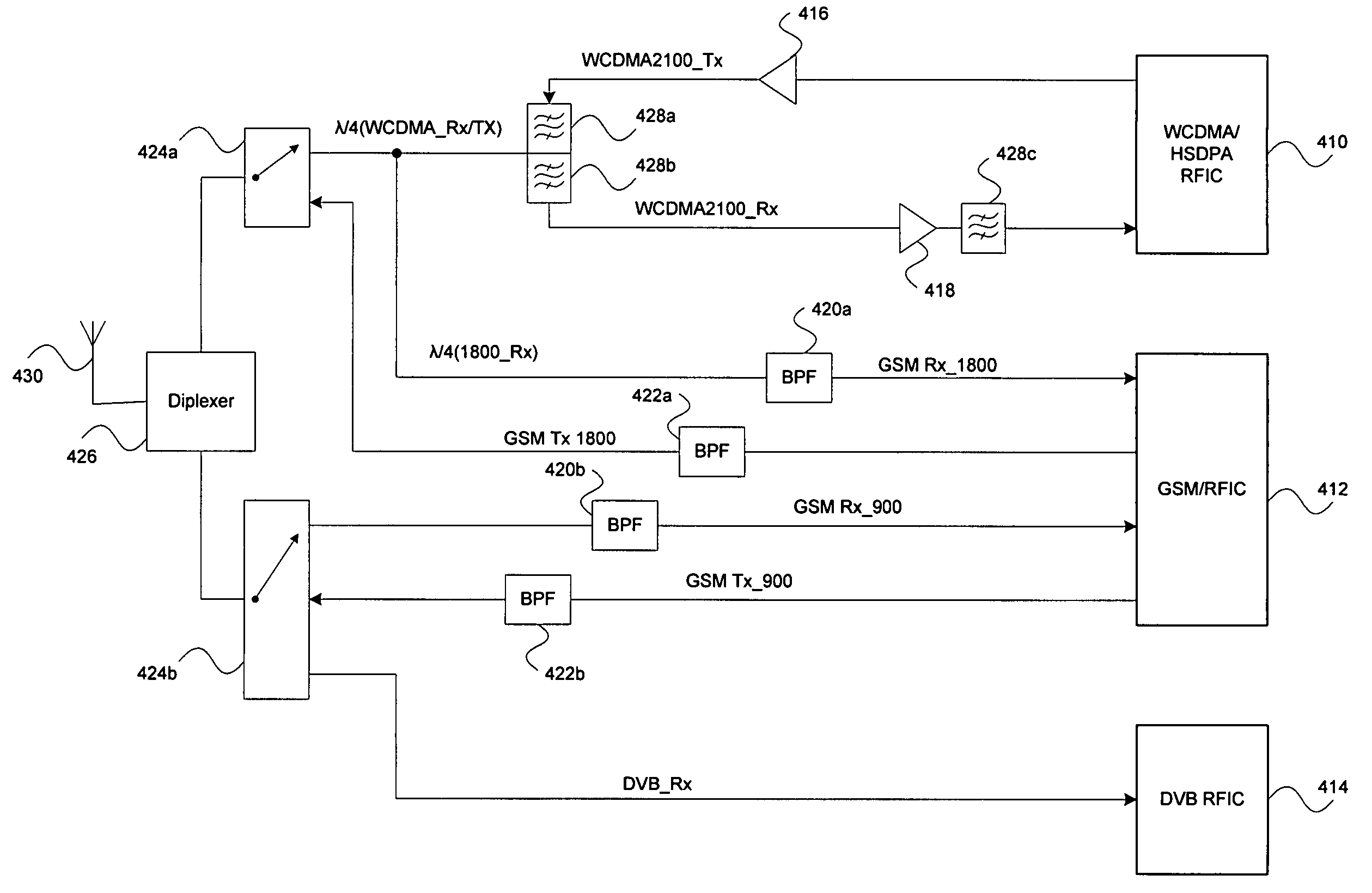
[0056]A method for an antenna architecture that handles European band cellular and broadcast channels may be provided. The method may comprise receiving at a first radio frequency integrated circuit (RFIC) integrated within a mobile terminal, first signals via a first antenna, where the first signals comprise signals within a 2100 MHz band. The method may further comprise receiving at a second RFIC integrated within the mobile terminal, second signals via the first antenna, where the second signals comprise signals within at least one of a 1800 MHz band and a 900 MHz band and receiving at a third RFIC integrated within the mobile terminal, third signals via the first antenna, where the third signals comprise signals within a VHF / UHF broadcast band.
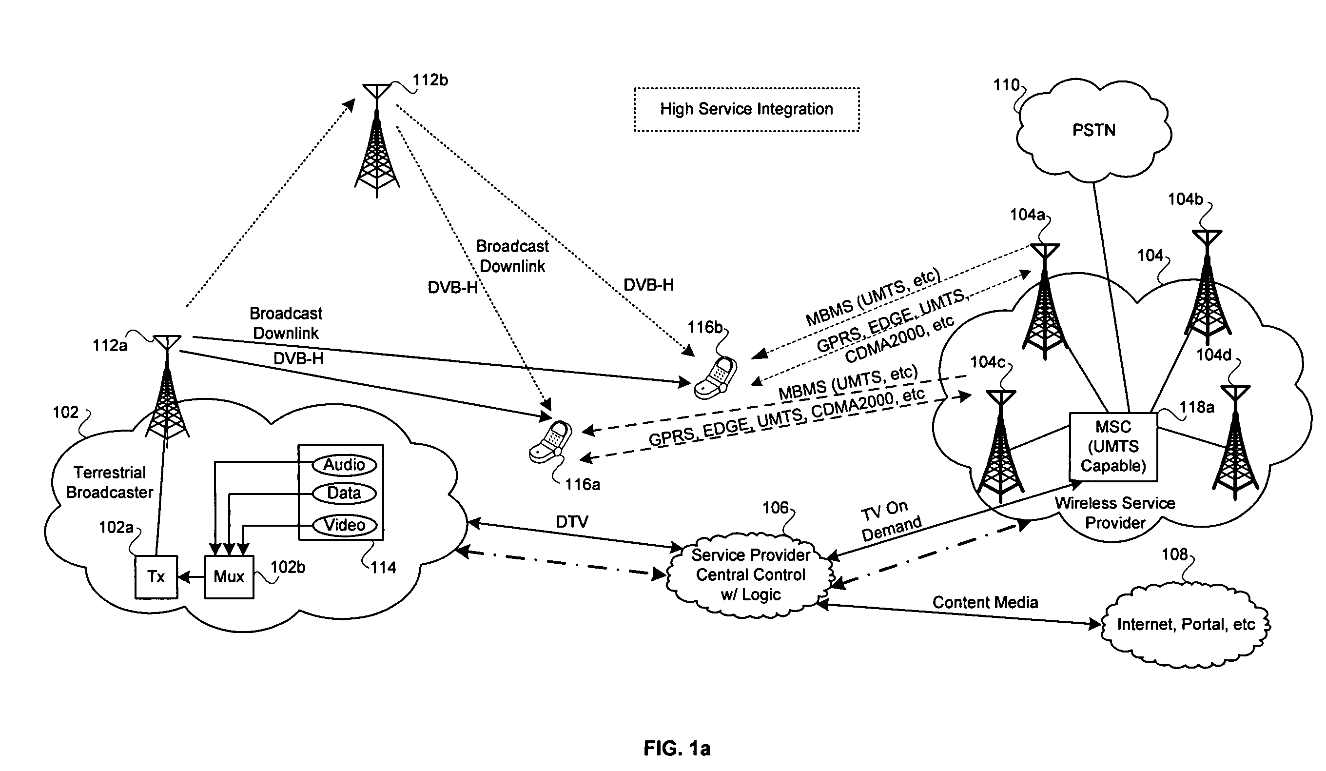
[0057]FIG. 1a is a block diagram of an exemplary system for providing integrated services between a cellular network and a digital video broadcast network, in accordance with an embodiment of the invention. Referring to FIG. 1a, there is s...
PUM
Abstract
A method for an antenna architecture that handles European band cellular and broadcast channels may be provided. The method may comprise receiving at a first radio frequency integrated circuit (RFIC) integrated within a mobile terminal, first signals via a first antenna, where the first signals comprise signals within a 2100 MHz band. The method may further comprise receiving at a second RFIC integrated within the mobile terminal, second signals via the first antenna, where the second signals comprise signals within at least one of a 1800 MHz band and a 900 MHz band and receiving at a third RFIC integrated within the mobile terminal, third signals via the first antenna, where the third signals comprise signals within a VHF / UHF broadcast band.
Application Information
Patent Timeline
Application Date:The date an application was filed.
Publication Date:The date a patent or application was officially published.
First Publication Date:The earliest publication date of a patent with the same application number.
Issue Date:Publication date of the patent grant document.
PCT Entry Date:The Entry date of PCT National Phase.
Estimated Expiry Date:The statutory expiry date of a patent right according to the Patent Law, and it is the longest term of protection that the patent right can achieve without the termination of the patent right due to other reasons(Term extension factor has been taken into account ).
Invalid Date:Actual expiry date is based on effective date or publication date of legal transaction data of invalid patent.

