Method of operating a double-sided scanner

a double-sided scanner and scanner technology, applied in the direction of solid-state devices, instruments, material analysis, etc., can solve the problems of flickering of images, unstable period of lamps, and high equipment costs of scanners, and achieve the effect of being switched on or off quickly

Inactive Publication Date: 2008-06-17
INTELLECTUAL VENTURES I LLC
View PDF16 Cites 17 Cited by
  • Summary
  • Abstract
  • Description
  • Claims
  • Application Information

AI Technical Summary

Benefits of technology

[0007]Accordingly, one object of the present invention is to provide a method of operating a double-sided scanner. This invention uses two groups of light sources (for example, light-emitting diodes) to serve as the light source for the double-sided scanner. Because the light-emitting diodes need no warm up period and can be switched on or off quickly, the scanner is able to scan two sides at the same time.
[0020]In brief, this invention utilizes two groups of light sources (for example, light-emitting diodes) to serve as the light source for a double-sided scanning device. Since light-emitting diodes need no warm-up period and can be switched on or off quickly, scanning both sides of a document concurrently is relatively simple.

Problems solved by technology

In the past, a scanner is an expensive piece of equipment that is deployed by a special user such as an artist.
However, the lamp has an unstable period after the scanner is activated.
If the lamp is used for scanning during the unstable period, a flickering of the image may occur.
However, one major disadvantage of using g cold cathode ray tube is that a longer warm-up period is required.
Aside from the long warming period, scanning of both sides of a document of an image simultaneously is not recommended because the light from the two sets of cold cathode ray tubes might interfere with each other.
Thus, if cold cathode ray tubes are used as the light source of a double-side scanner, complicated control circuits are demanded.

Method used


Image

  • Method of operating a double-sided scanner
  • Method of operating a double-sided scanner
  • Method of operating a double-sided scanner

Examples


Embodiment Construction

[0029]Reference will now be made in detail to the present preferred embodiments of the invention, examples of which are illustrated in the accompanying drawings. Wherever possible, the same reference numbers are used in the drawings and the description to refer to the same or like parts.

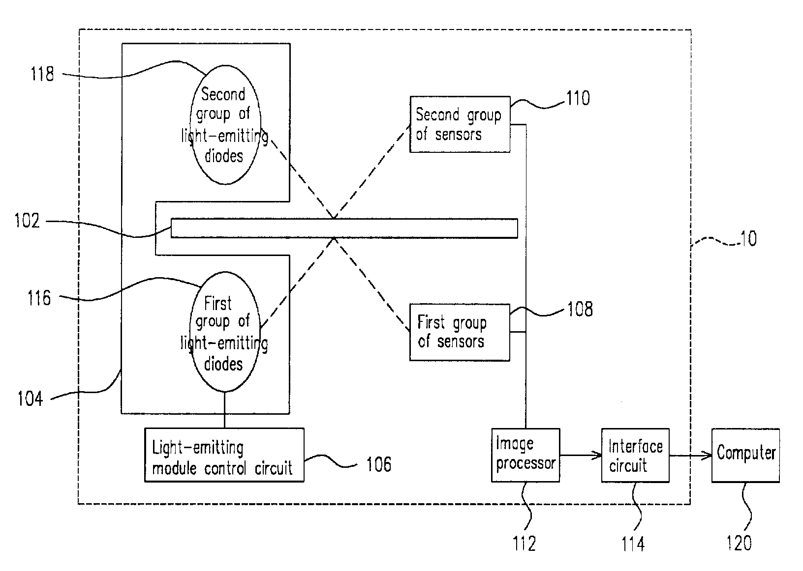
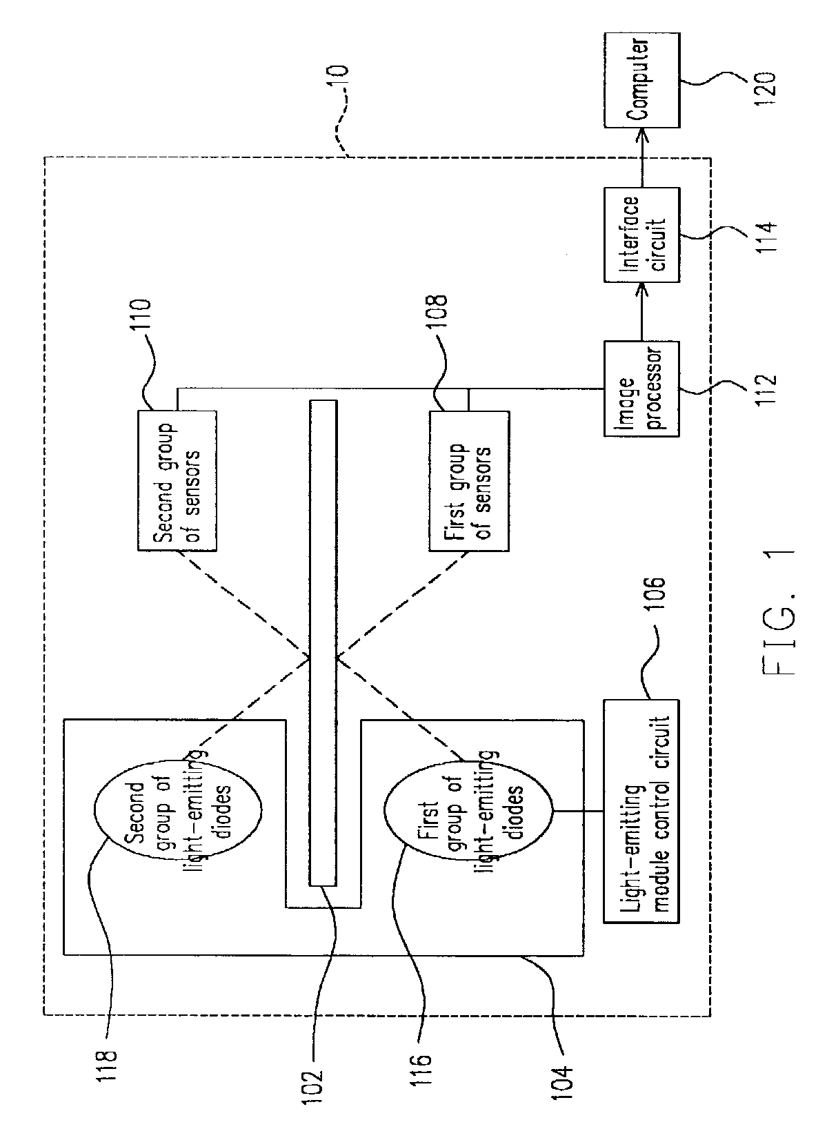
[0030]FIG. 1 is a schematic structural layout of a double-sided scanner according to a first preferred embodiment of this invention. As shown in FIG. 1, the double-sided scanner 10 is used for scanning a document 102. The double-sided scanner 10 includes a light-emitting module 104, a light emitting module control circuit 106, a first group of sensors 108 and a second group of sensors 110, an image processor 112 and an interface circuit 114. The light-emitting module 104 further includes a first group of light sources and a second group of light sources. In the following embodiment of this invention, the first group of light sources is a first group of light-emitting diodes 116 and the second group o...


PUM


Abstract

An operating method for a double-sided scanner is provided. A light source of one particular color inside a first group of light sources and a light source of a different color (or the same color) inside a second group of light source are lit to scan the front and back surface of a scan document. Optical signals from the front and back surface of the scan document are received and converted into analogue electrical signals. Thereafter, the analogue electrical signals are converted into digital electrical signal. Finally, the digital electrical signals are output to a host computer. This invention utilizes two groups of light sources (for example, light-emitting diodes) to serve as light sources for the double-sided scanner. Because light-emitting diodes require no warm-up period and is quick to switch, double-sided scanning is simplified.

Description

BACKGROUND OF INVENTION[0001]1. Field of Invention[0002]The present invention relates to a method of operating a scanner. More particularly, the present invention relates to a method of operating a double-sided scanner.[0003]2. Description of Related Art[0004]A scanner is a machine that can be regarded as an intermediate between a photocopier and a camera. In the past, a scanner is an expensive piece of equipment that is deployed by a special user such as an artist. With the progress in computer technologies, there is tremendous drop in the price of the scanner so that a scanner has become an essential peripheral device in most personal computers.[0005]According to the price or function, a scanner may be categorized into several types. In general, scanners can be divided into palm top scanners, paper feed scanners, card scanners, negative film scanners and flatbed scanners. A flatbed scanner has a glass platform for holding a document or a pattern thereon. Data is read into the scan...

Claims


Application Information

Patent Timeline
Patent Type & Authority Patents(United States)
IPC IPC(8): H04N1/04H04N1/203H04N1/48
CPCH04N1/04H04N2201/042
Inventor WANG, KUO-JENG
Owner INTELLECTUAL VENTURES I LLC
Why Eureka
Try Eureka