Tube fitting for stainless steel tubing

a technology of stainless steel tubing and fittings, which is applied in the direction of hose connections, sleeves/socket joints, mechanical equipment, etc., can solve the problems of difficult design in order to achieve the desired tube grip and seal function, difficult to grip heavy wall tubing, etc., to achieve improved sealing function, improved tube grip, and excellent tube grip function

Inactive Publication Date: 2008-07-01
SWAGELOK CO
View PDF237 Cites 24 Cited by
  • Summary
  • Abstract
  • Description
  • Claims
  • Application Information

AI Technical Summary

Benefits of technology

[0023]In accordance with one aspect of the invention, a single ferrule tube fitting for stainless steel tubing is provided that achieves a significantly improved sealing function over prior single ferrule tube fittings while also achieving an excellent tube grip function. This sealing function is achieved without the use of additional elastomeric or other non-metal seals. In one embodiment, the single ferrule tube fitting utilizes a relatively steep camming angle for the camming surface of the fitting body. In accordance with this aspect of the invention, in one embodiment the camming angle is in the range of at least about 35 degrees to about 60 degrees, and preferably in the range of about forty to about fifty degrees and most preferred to be about forty-five degrees. In accordance with another aspect of the invention, a single ferrule tube fitting is provided that provides a primary seal against a relatively steeply angled camming surface. In the main embodiment this seal is formed by an outer tapered surface of the ferrule, that is not as steeply angled as the camming surface, being plastically deformed or coined with a generally narrow line contact against a camming surface angle within the above noted range. In accordance with another aspect of the invention, a single ferrule tube fitting with improved tube grip is contemplated by utilizing a case hardened ferrule with a geometry designed to enhance the ferrule tube grip. In one embodiment, the ferrule is case hardened to be at least about 3.3 times harder than the stainless steel tubing, more preferably at least 4 times harder than the stainless steel tubing. This allows the single ferrule to adequately bite into the hard stainless steel surface to grip the tube end even with a steeper camming angle and less axial travel. In accordance with another aspect of the invention, the single ferrule is plastically deformed during pull-up with a hinging effect. This hinging action produces a radially inward compression on a central or mid-portion of the ferrule body axially from a front end of the ferrule that bites into the tube end. This hinging effect places more ferrule material at the location of the tube gripping bite and produces a collet-type or swaging action of the central or mid-portion of the ferrule that helps isolate the tube gripping bite from vibration effects. In one embodiment, the ferrule geometry includes at least one interior circumferential recess to enhance the hinging action during pull-up. The hinging action also helps to keep the ferrule outer tapered surface to have a generally narrow line contact with the camming surface.
[0024]The present invention is also directed to a new tube fitting concept that utilizes the steeper camming angle and requires user assembly of only two components, namely a fitting body and a fitting nut. The nut and body are adapted to be threadably coupled together by relative rotation therebetween. The nut includes an integral tube gripping ring that cooperates with a camming surface on the body when the fitting is made-up. The ring may be machined with the nut or separately attached thereto by any convenient process such as brazing, welding or soldering, for example. The ring is radially compressed and plastically deformed against the tube outer wall to form a seal and a tight tube grip bite. The ring also forms a primary seal against the steeper camming surface. In one embodiment, the ring includes an outer tapered surface, that is not as steep as the camming surface angle, forming a generally narrow line contact-type seal against the steeper camming surface. The ring in one embodiment is designed to have a hinging action and to plastic deform during pull-up to embed the nose portion into the tubing wall for excellent tube grip, and an axially adjacent swage or collet zone that isolates the embedded nose portion from vibration effects. The fitting components, and particularly the ring, are preferably but not necessarily case hardened. The new fitting is especially useful as a stainless steel tube fitting, although the invention is not limited to any particular class of metals. In accordance with another aspect of the invention, the fitting may include a self-gauging feature to indicate sufficient pull-up and to prevent excessive tightening of the components.

Problems solved by technology

Secondly, the tube fitting must maintain a primary seal against leakage.
Tube fittings that are intended for use with stainless steel tubing, for example, are particularly challenging to design in order to achieve the desired tube grip and seal functions.
Heavy wall tubing is difficult to grip because it is not only hard but it is also not particularly ductile.
Low ductility makes it more difficult to deform the tubing plastically so as to achieve a desired tube grip.
These designs are not suitable for high pressure stainless steel tube fittings.
However, it is becoming increasingly recognized that these two functions are at odds with each other when designing a tube fitting that can meet a desired tube grip and seal performance criteria.
This is because the design criteria needed to assure that the tube fitting achieves an adequate tube grip usually works against the ability of the single ferrule to also provide an effective seal.
Consequently, although prior art single ferrule fittings can achieve adequate tube grip in some cases, this tube grip performance comes at the expense of having a less effective seal.
Single ferrule tube fittings thus are usually more suited to lower pressure liquid applications such as hydraulics, however, even in such lower pressure applications single ferrule seal performance remains less than desired.
Consequently, an outwardly bowed single ferrule fitting could be more susceptible to ferrule collapse, loss of seal and possibly tube blow out at higher pressures.
The result in such cases however is a low grip or low pressure only fitting that are not well suited to stainless steel fittings.
The shallow camming angle and elongated camming surface and axial movement needed to achieve an adequate tube grip with a single ferrule fitting, however, compromises the ability of the single ferrule to achieve the seal function, especially in extreme environments and for sealing gas.
This enlarged seal area causes an unwanted distribution of the sealing force between the single ferrule and the camming surface, and also creates a larger area for surface imperfections to allow leaks to occur.
The fitting does not appear to be applicable to stainless steel tubing as the tube is covered with a resin cover.

Method used


Image

  • Tube fitting for stainless steel tubing
  • Tube fitting for stainless steel tubing
  • Tube fitting for stainless steel tubing

Examples


Embodiment Construction

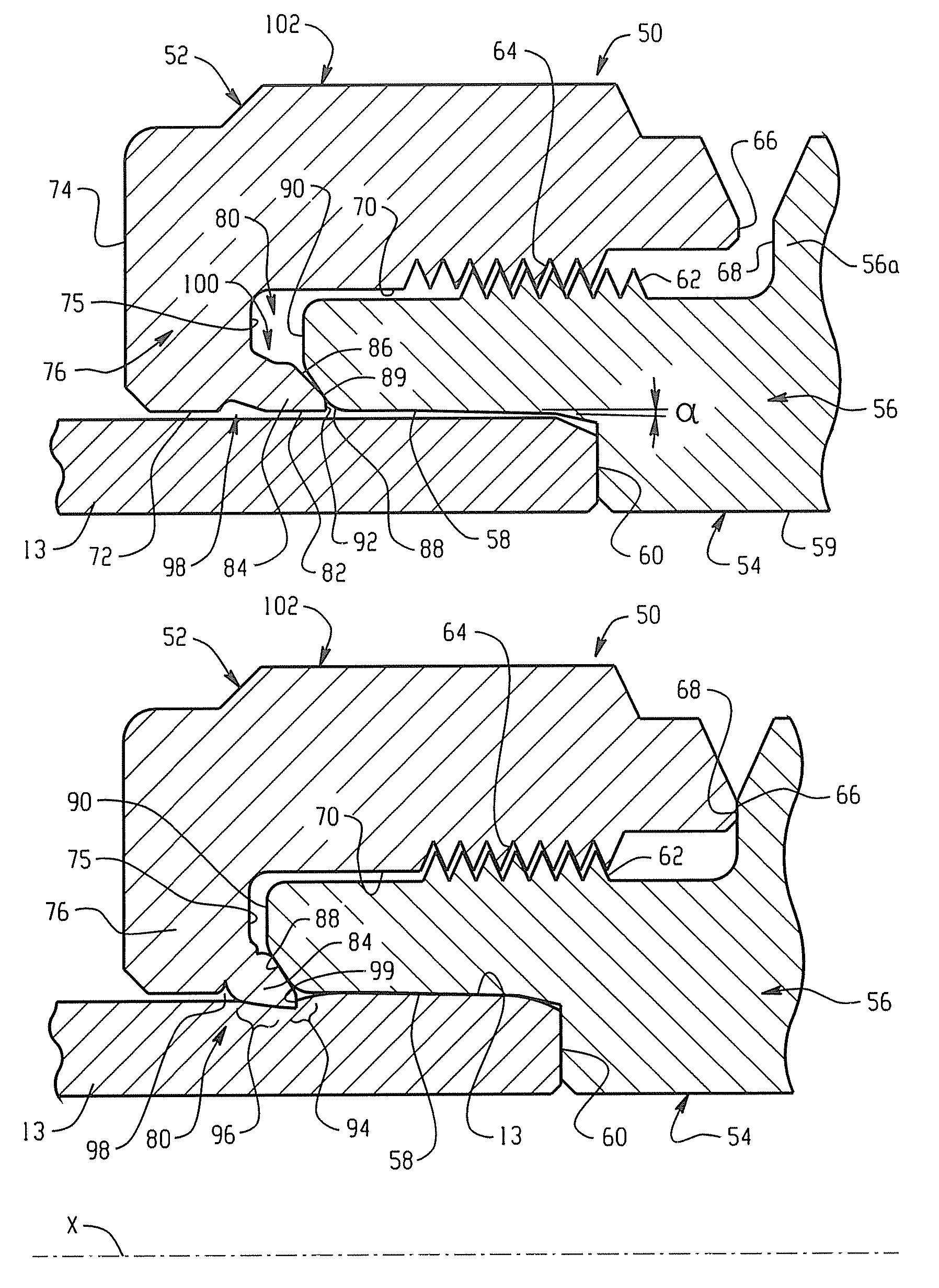
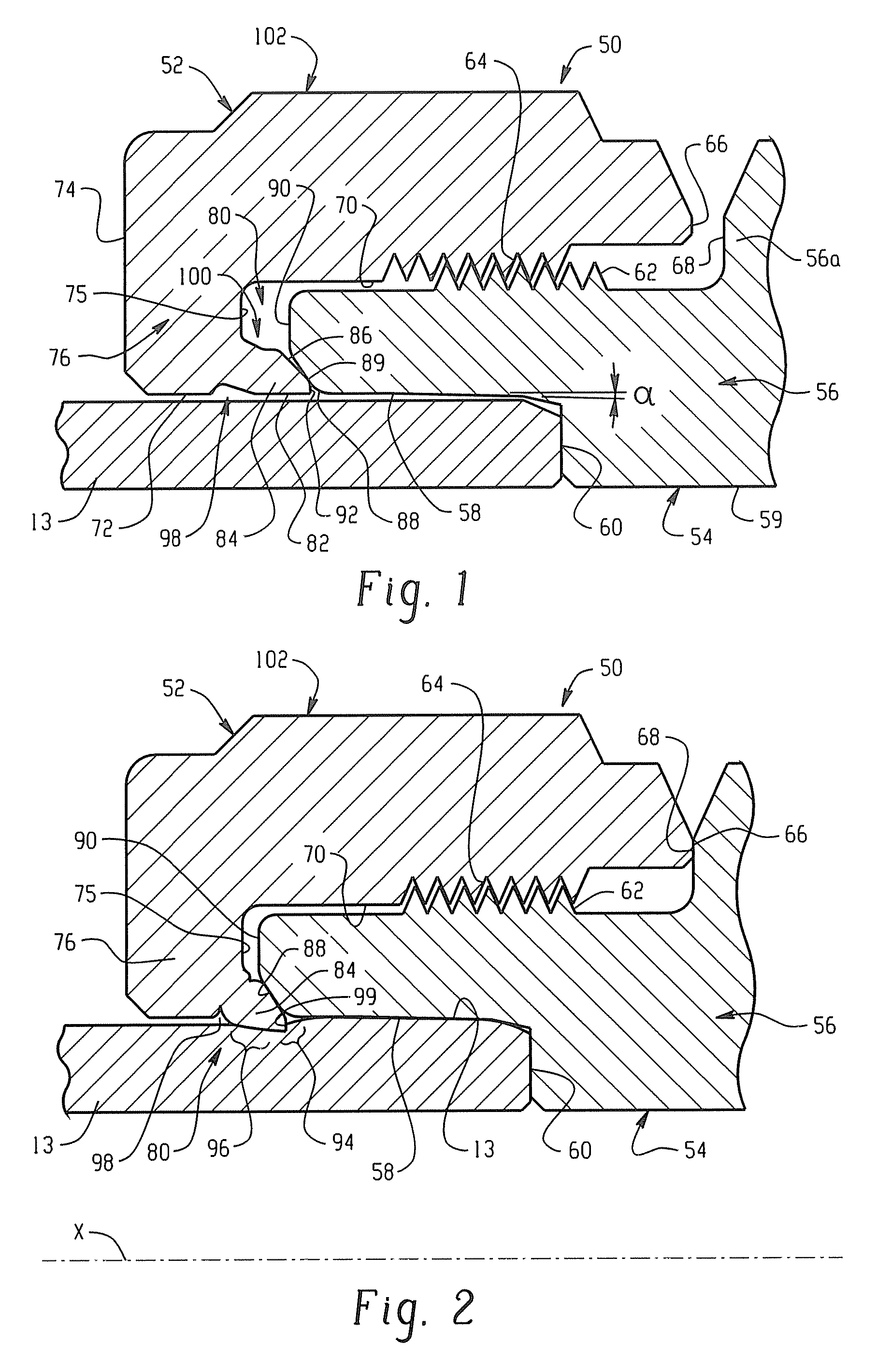
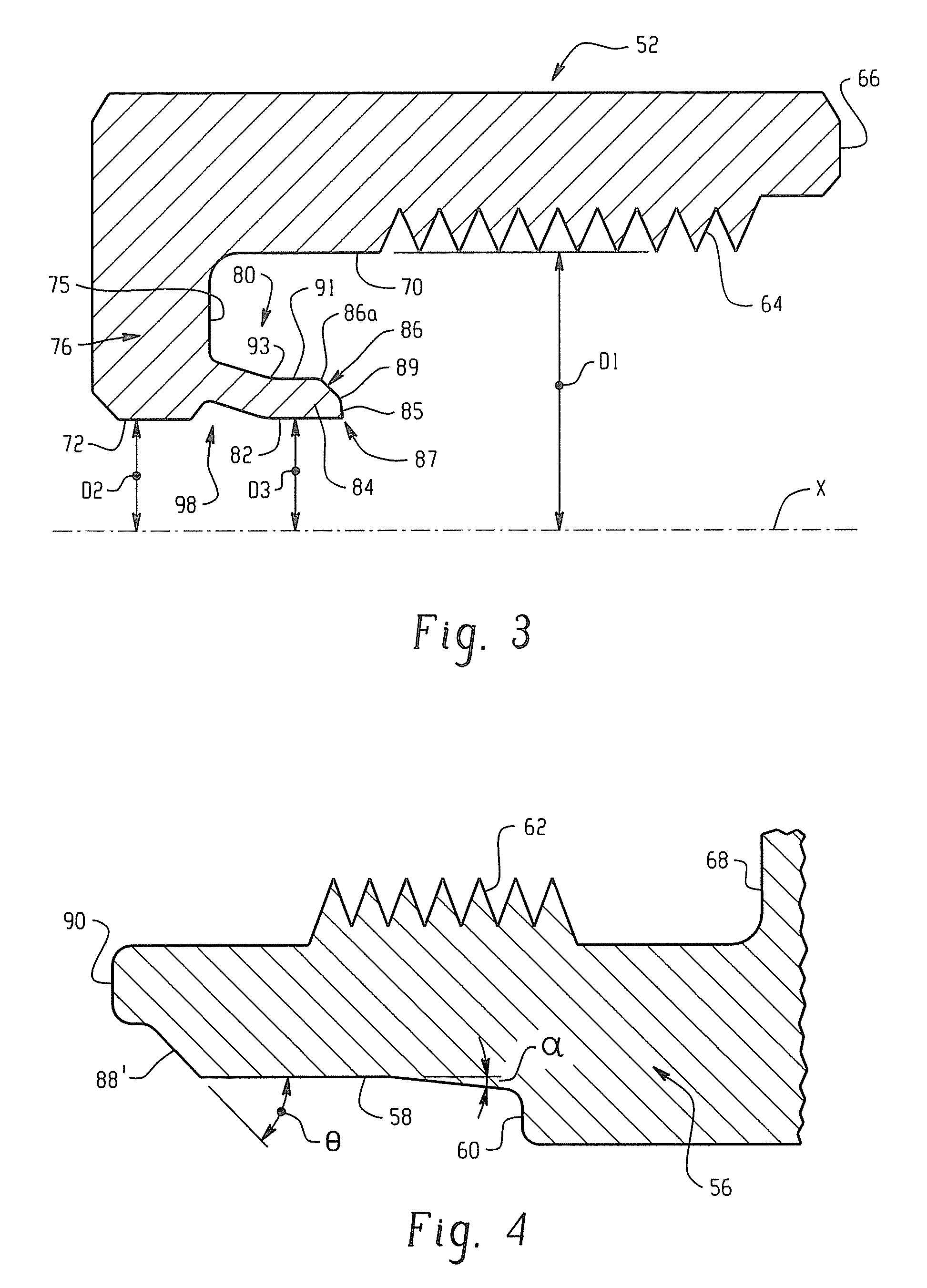
[0034]In accordance then with one aspect of the invention, a tube fitting is provided having a tube gripping device that acts against a steep camming angle surface of one of the fitting components. The steep camming surface angle is particularly advantageous when the hardness of the tube gripping device has a ratio of at least about 3.3 times greater and preferably at least 4 times greater to the hardness of the tubing material. The present disclosure utilizes these aspects of the invention in two distinct general embodiments. The first general embodiment that will be described is a tube fitting arrangement in which a tube gripping device is provided that is integral with one of the two threaded components, namely the female threaded nut component. The second general embodiment is that of a tube fitting for stainless steel tubing that uses a separate single ferrule as the tube gripping device along with the male and female threaded components. Both general embodiments may share a nu...


PUM

PropertyMeasurementUnit
included angleaaaaaaaaaa

Abstract

A tube fitting that uses only two components, namely a fitting body and a fitting nut. The nut and body are adapted to be threadably coupled together by relative rotation therebetween. The nut includes an integral tube gripping ring that cooperates with a camming surface on the body when the fitting is made-up. The camming surface preferably has a steep camming angle. The ring is radially compressed against the tube outer wall to form a seal and a tight tube grip. The ring also forms a line contact-type seal against the camming surface. The ring is designed to have a hinging action and to plastically deform during pull-up to embed into the tubing for excellent tube grip, and an axially adjacent swage or collet zone that isolates any stress riser resulting from the embedding action from vibration effects. The fitting components, and particularly the ring, may be case hardened, the fitting may include a self-gauging feature to indicate sufficient pull-up to prevent excessive pull-up. Also provided is a single ferrule tube fitting that uses a steep camming surface and is at least about 3.3 times harder than the stainless steel tube end.

Description

RELATED APPLICATIONS[0001]This application claims the benefit of U.S. Provisional patent application Ser. No. 60 / 266,735 filed on Feb. 6, 2001 for TUBE FITTING WITH INTEGRAL NUT AND FERRULE, the entire disclosure of which is fully incorporated by reference.TECHNICAL FIELD OF THE INVENTION[0002]The subject invention is generally directed to the art of tube fittings for stainless steel tubing. More particularly, the invention is directed to flareless tube fittings that include a steep angle camming surface.BACKGROUND OF THE INVENTION[0003]Tube fittings are used to join or connect a tube end to another member, whether that other member be another tube end such as through T-fittings and elbow fittings, for example, or a device that needs to be in fluid communication with the tube end, such as for example, a valve. As used herein the terms “tube” and “tubing” are intended to include but not be limited to pipe as well. Any tube fitting must accomplish two important functions within the pr...

Claims


Application Information

Patent Timeline
Patent Type & Authority Patents(United States)
IPC IPC(8): F16L33/00F16L19/08F16L19/065F16L19/10F16L21/08
CPCF16L19/14F16L19/10F16L19/04
Inventor WILLIAMS, PETER C.
Owner SWAGELOK CO
Why Eureka
Try Eureka