Vehicle sun visors with support rods

a technology of support rods and visors, which is applied in the direction of roofs, superstructures, monocoque constructions, etc., can solve the problems of complicated construction of outer sleeves, and achieve the effect of assembly operation

Inactive Publication Date: 2008-12-02
KYOWA SANGYO +1
View PDF3 Cites 4 Cited by
  • Summary
  • Abstract
  • Description
  • Claims
  • Application Information

AI Technical Summary

Benefits of technology

[0011]It is accordingly an object of the present invention to teach vehicle sun visors having a support rod that is simple in construction while causing minimal radial displacement of the outer sleeve relative to a core rod member.
[0013]With this arrangement, the first and second semi-circular cylindrical sleeve halves may be assembled into the outer sleeve when their resilient engaging portions engage with the outer peripheral surface of the core rod member. Since the first and second semi-circular cylindrical sleeve halves constituting the outer sleeve are directly engaged with the outer peripheral surface of the core rod member in order to configure the rotatably support rod, possible displacement of the outer sleeve in the radial direction relative to the core rod member can be minimized.
[0015]Therefore, the resilient engaging portion can be easily engaged with the outer peripheral surface of the core rod member by the resilient deformation of the first and second engaging claws that are resiliently deformed open and then engaged with the outer peripheral surface of the core rod member. For example, pressing the first and second engaging claws against the outer peripheral surface of the core rod member may cause such resilient deformation of the first and second engaging claws. Therefore the assembly operation of the first and second semi-circular cylindrical sleeve halves can be easily performed.
[0018]This configuration also allows the molding of the first and second semi-circular cylindrical sleeve halves by the same molding die. In addition, the assembly operation and the product control of the first and second semi-circular cylindrical sleeve halves may be readily facilitated. Therefore, the result is effective cost reduction.
[0020]As a result of this arrangement, it is not necessary to orient the first and second semi-circular cylindrical sleeve halves in opposing directions for fitting onto the outer peripheral surface of the core rod member. Therefore, the assembly operation of the first and second semi-circular cylindrical sleeve halves may be further facilitated.

Problems solved by technology

In addition, if displacement prevention portions are formed on the first and second sleeve halves, the construction of the outer sleeve may become complicated.

Method used


Image

  • Vehicle sun visors with support rods
  • Vehicle sun visors with support rods
  • Vehicle sun visors with support rods

Examples


first representative embodiment

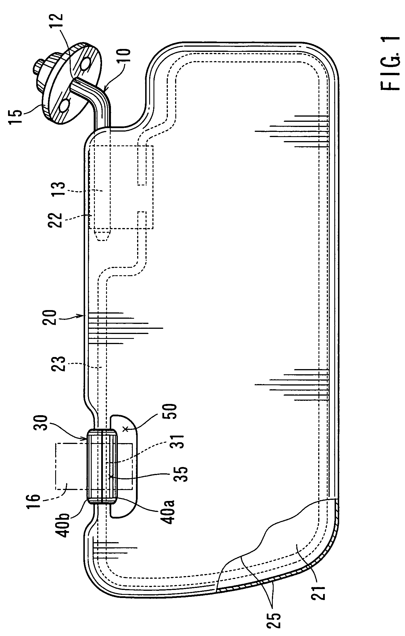
[0034]Referring to FIG. 1, a first representative sun visor generally includes a visor body 20 and a first support rod 10. The support rod 10 has a substantially L-shaped configuration and includes a vertical rod portion 12 integrated with a horizontal rod portion 13. The vertical rod portion 12 is mounted to a vehicle cabin ceiling (not shown) at a suitable position via a bracket 15. The visor body 20 is configured so as to have a predetermined configuration. The visor body 20 includes a core member 21 and a surface cover sheet 25 covering an outer surface of the cover member 21. A bearing member 13 is disposed within the core member 21 at a position adjacent to one of corners of the core member 21. The horizontal portion 13 of the first support rod 10 is rotatably inserted into the bearing member 13. The visor body 20 can pivot about the horizontal portion 13 to move between a storage position along the vehicle cabin ceiling and a front light-shielding position adjacent to a winds...

second representative embodiment

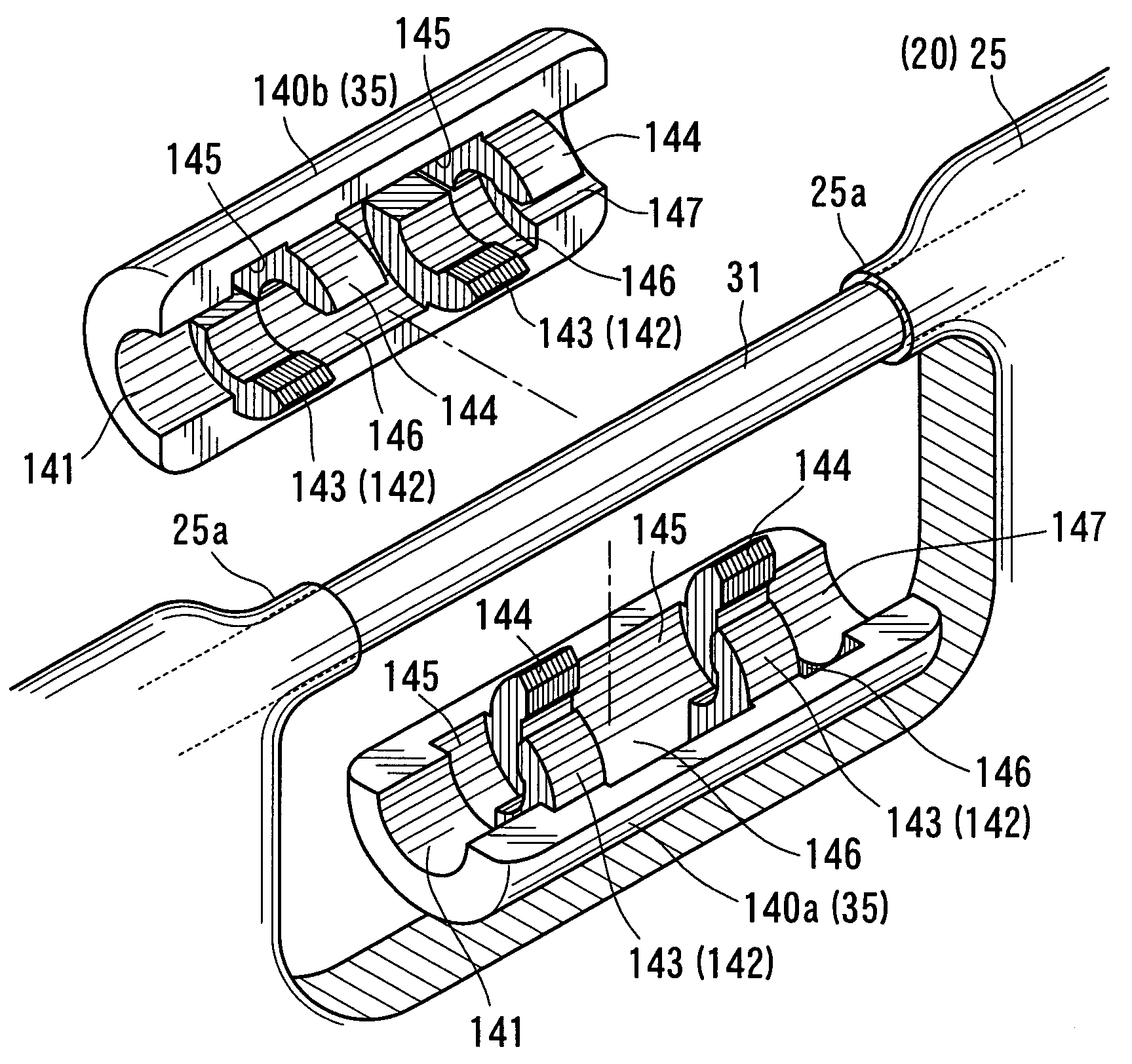
[0046]A second representative embodiment will now be described with reference to FIGS. 7 to 11. The second representative embodiment is a modification of the first representative embodiment. Therefore, like members are given the same reference numerals as in the first representative embodiment and the description of these members will not be repeated.

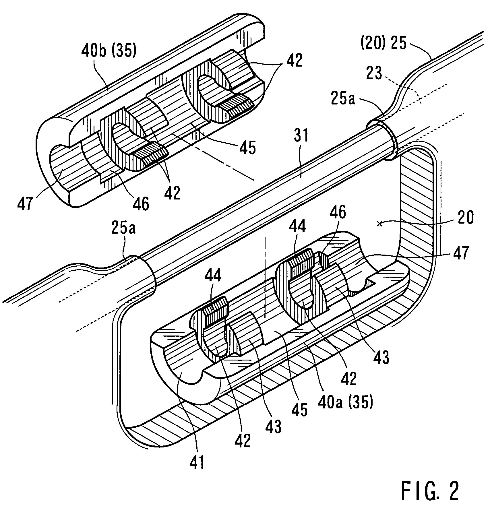
[0047]This representative embodiment relates to an improvement of the first representative embodiment for eliminating the directional limitation of the first and second semi-circular cylindrical sleeve halves 40a and 40b of the outer sleeve 35 of the second support rod 30.

[0048]Also in this representative embodiment, first and second semi-circular cylindrical sleeve halves 140a and 140b (corresponding to the first and second semi-circular cylindrical sleeve halves 40a and 40b of the first representative embodiment) are molded from resin to have the same configuration with one another. Each of the first and second semi-circular cylindric...

embodiment

Other Possible Embodiment

[0055]The present invention may not be limited to the above first and second representative embodiments but may be modified in various ways. For example, although each of the first and second semi-circular cylindrical sleeve halves 40a and 40b (140a and 140b) of the outer sleeve 35 has two resilient engaging portions 42 (142), the number of the resilient engaging portions may not be limited to two. One or three or more resilient engaging portions may be provided.


PUM


Abstract

A vehicle sun visor including a visor body and a support rod disposed on the visor body. The support rod is adapted to engage a support hook mounted to a vehicle cabin ceiling. The support rod includes a core rod member mounted on the visor body and an outer sleeve disposed on the outer peripheral side of the core rod member. The outer sleeve includes first and second semi-circular cylindrical sleeve halves each having at least one resilient engaging portion formed integrally therewith. The resilient engaging portions resiliently engage an outer peripheral surface of the core rod member. The semi-circular cylindrical sleeve halves may have similar configurations with each other.

Description

[0001]This application claims priority to Japanese patent application serial number 2004-157249, the contents of which are incorporated herein by reference.BACKGROUND OF THE INVENTION[0002]1. Field of the Invention[0003]The present invention relates to vehicle sun visors, and in particular to vehicle sun visors having a visor body and a support rod provided on the visor body for engagement with a support hook mounted to a vehicle cabin ceiling.[0004]2. Description of the Related Art[0005]A known vehicle sun visor has a visor body as a major element. The visor body is rotatably supported by a horizontal rod portion of a first support rod that is supported on a vehicle cabin ceiling via a bracket. Therefore, the visor body can move between a storage position along the vehicle cabin ceiling and a light-shielding position along a windshield as the visor body rotates relative to the horizontal rod portion of the first support rod.[0006]In order to enable the visor body to stably rotate, ...

Claims


Application Information

Patent Timeline
Patent Type & Authority Patents(United States)
IPC IPC(8): B60J3/00B60J3/02
CPCB60J3/0204B60J3/023
Inventor TORII, HIDEKAZU
Owner KYOWA SANGYO
Why Eureka
Try Eureka