Disk drive demodulating a time-based servo pattern

a time-based servo pattern and disk drive technology, applied in the field of disk drives, can solve problems such as signal loss

Inactive Publication Date: 2009-03-10
WESTERN DIGITAL TECH INC
View PDF12 Cites 118 Cited by
  • Summary
  • Abstract
  • Description
  • Claims
  • Application Information

AI Technical Summary

Benefits of technology

[0015]Another embodiment of the present invention comprises a method of operating a disk drive, the disk drive comprising a disk having a first set of time-based servo patterns and a second set of time-based servo patterns that define a plurality of servo tracks. The first set of time-based servo patterns comprises a first cyclical pattern that repeats radially over the disk, and the second set of time-based servo patterns comprises a second cyclical pattern that repeats radially over the disk, wherein each cyclical pattern comprises a plurality of timing marks. One of the first cyclical patterns overlaps at least part of a first servo track, and one of the second cyclical patterns overlaps at least part of the first servo track. A head is positioned over the disk by demodulating at least one of the first and second set of time-based servo patterns. A first and second time intervals are detected relative to the timing marks, and a control signal for actuating the head is generated in response to the first and second time intervals.

Problems solved by technology

However, when using the time-based servo pattern shown in FIG. 1B, there is signal loss when the head 16 is positioned between the tracks of adjacent servo patterns.

Method used


Image

  • Disk drive demodulating a time-based servo pattern
  • Disk drive demodulating a time-based servo pattern
  • Disk drive demodulating a time-based servo pattern

Examples


Embodiment Construction

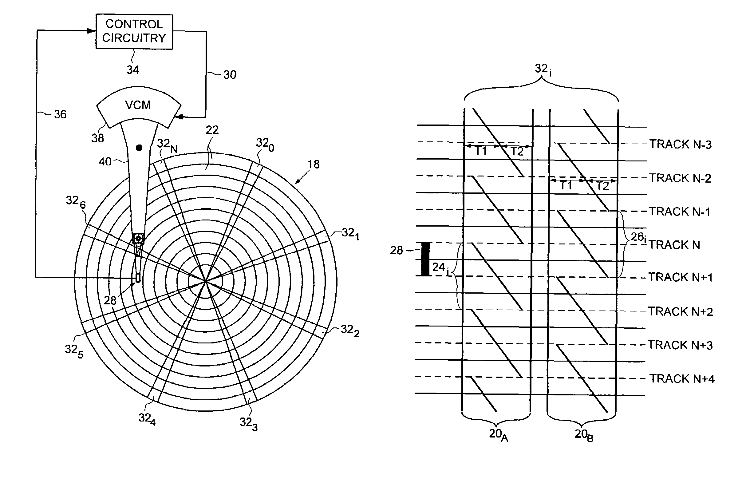
[0023]FIGS. 2A and 2B show an embodiment of the present invention as a disk drive including a disk 18 comprising a first set of time-based servo patterns 20A and a second set of time-based servo patterns 20B that define a plurality of servo tracks 22. The first set of time-based servo patterns 20A comprises a first cyclical pattern 24i that repeats radially over the disk 18, and the second set of time-based servo patterns 20B comprises a second cyclical pattern 26i that repeats radially over the disk 18, wherein each cyclical pattern comprises a plurality of timing marks. One of the first cyclical patterns 24i overlaps at least part of a first servo track (e.g., servo track N+1), and one of the second cyclical patterns 26i overlaps at least part of the first servo track. A head 28 is positioned over the disk 18 by demodulating at least one of the first and second set of time-based servo patterns 20A and 20B. A first and second time intervals (e.g., T1 and T2) are detected relative t...


PUM

PropertyMeasurementUnit
time-aaaaaaaaaa
timeaaaaaaaaaa
frequencyaaaaaaaaaa

Abstract

A disk drive is disclosed including a disk having a first and second set of time-based servo patterns. The first set of time-based servo patterns comprises a first cyclical pattern that repeats radially over the disk, and the second set of time-based servo patterns comprises a second cyclical pattern that repeats radially over the disk, wherein each cyclical pattern comprises a plurality of timing marks. One of the first cyclical patterns overlaps at least part of a first servo track, and one of the second cyclical patterns overlaps at least part of the first servo track. At least one of the first and second set of time-based servo patterns are demodulated by detecting first and second time intervals relative to the timing marks, and a control signal for actuating the head is generated in response to the first and second time intervals.

Description

BACKGROUND[0001]1. Field[0002]The present invention relates to disk drives for computer systems. More particularly, the present invention relates to a disk drive demodulating a time-based servo pattern.[0003]2. Description of the Related Art[0004]A disk drive comprises a head attached to a distal end of an actuator arm which is rotated about a pivot to actuate the head radially over a disk. The disk typically comprises embedded servo sectors including head positioning information used to seek the head to a target track and maintain the head over the track during write / read operations. FIG. 1A shows a prior art format of a disk 2 comprising a plurality of embedded servo sectors 40-4N that define a plurality of radially spaced, concentric servo tracks 6. Each servo sector 4i comprises a preamble 8 for synchronizing timing recovery to the data rate, and a sync mark 10 for symbol synchronizing to a servo data field 12, where the servo data field 12 typically comprises a servo track addr...

Claims


Application Information

Patent Timeline
Patent Type & Authority Patents(United States)
IPC IPC(8): G11B5/596G11B5/09
CPCG11B5/59655
Inventor CHUE, JACK M.
Owner WESTERN DIGITAL TECH INC
Why Eureka
Try Eureka