Indicator control system with camera section

a control system and camera section technology, applied in the direction of television systems, identification means, instruments, etc., can solve the problems of obstructing the front field of vision, affecting the operation of the operator, and limiting the space of the driver's cabin, so as to improve the operation efficiency and improve the operation efficiency. , the effect of smooth switching of display modes

Inactive Publication Date: 2009-10-20
CATEPILLAR SARL
View PDF21 Cites 22 Cited by
  • Summary
  • Abstract
  • Description
  • Claims
  • Application Information

AI Technical Summary

Benefits of technology

[0017]In the indicator control system with a camera section in accordance with the present invention, since the measurement value display mode and the camera display mode can be displayed on one indicator by being switched, the space in a cab can be saved, and also good front visibility can be secured.
[0018]Also, the display mode can be switched smoothly by the operation of a switch provided on the indicator or an operation member.
[0019]Further, since the camera section can carry out control such as the control of the photographing direction or the control of zooming in and out by a remote control switch provided on the indicator, the monitoring area can be made variable or the image can be enlarged, which contributes to safety.

Problems solved by technology

However, the space of the driver's cabin is limited, so that a problem arises in that a display for showing camera images provided separately from the gage and the indicator obstructs the front field of vision.
Also, even in the case where alarm information is shown on a separate monitor for monitoring the equipment information, a problem arises in that it is difficult for the operator to become aware of the alarm information when he / she is paying attention to the display for camera.
However, conventionally, the rear monitoring camera has been operated by the operation of a running lever, and a method for monitoring the directions other than the rear has not been developed, so that the camera has poor flexibility.
Also, the camera has been fixed, and the movement of photographing position has not been thought, which poses a drawback in that the monitoring area is limited.

Method used


Image

  • Indicator control system with camera section
  • Indicator control system with camera section
  • Indicator control system with camera section

Examples


example 1

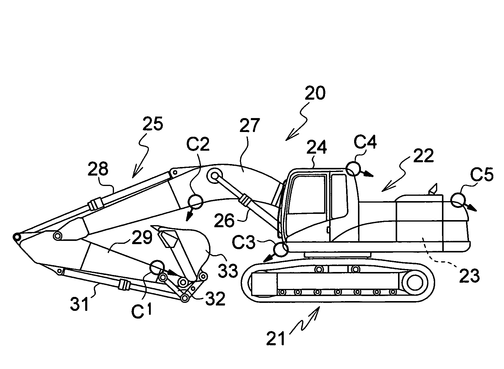
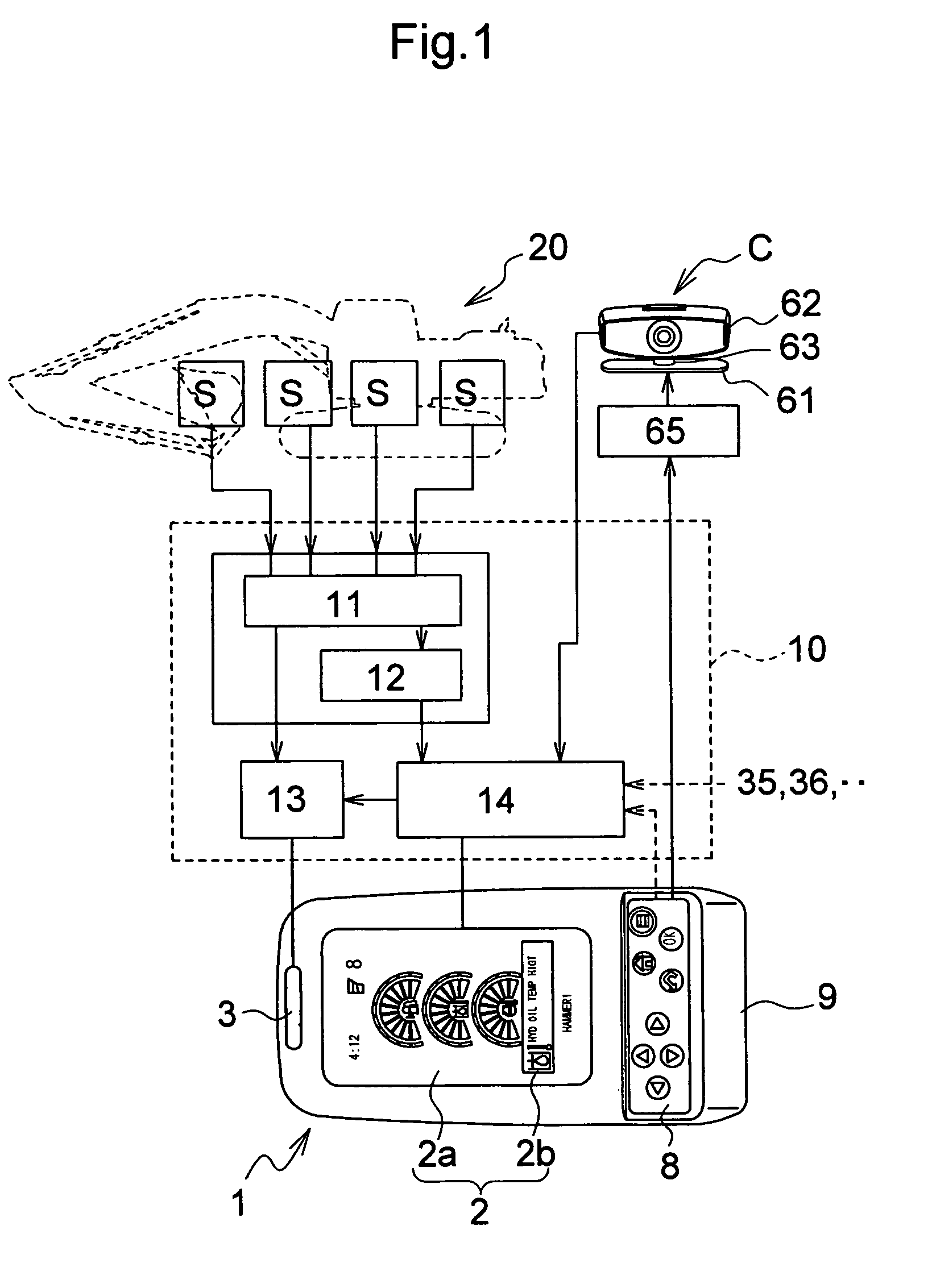
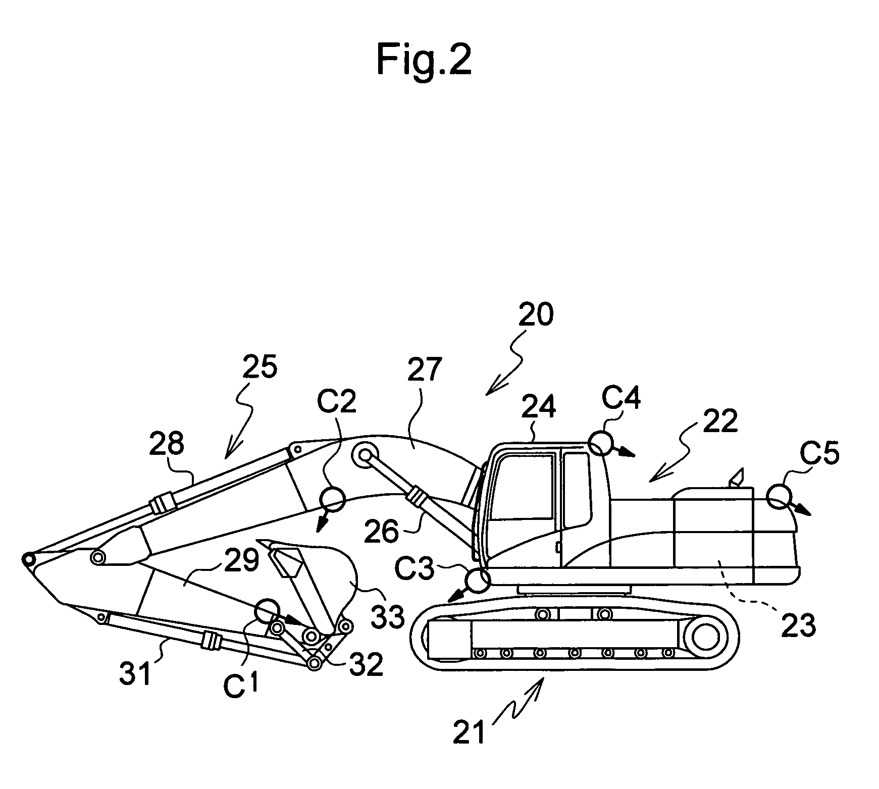
[0050]An indicator control system with a camera section shown in FIG. 1 includes an indicator 1 provided in a cab, a sensor group S, S, S . . . which is provided on predetermined components of a hydraulic excavator 20 to obtain measurement data, a monitoring camera C mounted at a predetermined location of the hydraulic excavator 20, and a controller 10 which allows images to be displayed in a monitor section 2 of the indicator 1 based on the measurement data to control the activation of an alarm section 3.

[0051]In the case of this example, the controller 10 includes an alarm judging means 11 for judging whether or not the measurement data from the sensor group S, S, S . . . corresponds to a preset alarm standard (in other words, whether or not the measurement data is included in the normal region), an image processing means 12 for converting the measurement data into a gage image, an alarm control means 13 for determining a pattern control of alarm to the alarm section 3, and an inp...

example 2

[0108]Also, in the above-described example, the configuration in which whether or not the alarm is necessary is not judged from the data of the camera section C is exemplarily shown. However, the configuration may be such that whether or not the alarm is necessary is judged based on the data of the camera section C.

[0109]The configuration may be such that, for example, during the work, the camera section C is allowed to be activated always or during predetermined work, and when an obstacle is detected in a predetermined monitoring area displayed on the camera section C, whether or not the alarm is necessary is judged by a camera alarm judging means 11′, and an alarm is generated in the same way.

[0110]In the indicator control system with a camera section shown in FIG. 6, the image data of the camera section C is sent to the camera alarm judging means 11′, and it is judged whether or not the obstacle displayed on the image data is safe.

[0111]When it is judged that an alarm is necessar...


PUM


Abstract

An indicator control system with a camera section provided with a switch for switching from a measurement value display mode to a camera display mode and vice versa to display a selected mode on a monitor section of an indicator. The measurement value display mode shows the measurement data of an object to be monitored on a construction machine, and the camera display mode is for the camera section mounted on the construction machine.

Description

TECHNICAL FIELD[0001]The present invention relates to an improvement of an indicator control system having a camera section for switching from a measurement value display mode to a camera display mode and vice versa to display a selected mode on a monitor section of an indicator, the measurement value display mode showing the measurement data of an object to be monitored of a construction machine, and the camera display mode being for the camera section mounted on the construction machine.BACKGROUND ART[0002]In the case where a monitoring camera is used as an auxiliary means for performing work using a construction machine safely and smoothly, it is necessary to provide a display for showing the image of the camera in a driver's cabin (for example, Japanese Patent Provisional Publication No. 2002-294762).[0003]On the other hand, for an indicator of the construction machine, especially a hydraulic excavator, not only fuel and engine cooling water but also the temperature of hydraulic...

Claims


Application Information

Patent Timeline
Patent Type & Authority Patents(United States)
IPC IPC(8): B60Q1/00G05D1/02G09F9/00H04N7/18B60R1/00E02F9/20E02F9/24E02F9/26
CPCE02F9/26
Inventor YAMADA, HIDEOMUROTA, ISAOONO, TOMOAKIFUJII, SATOSHI
Owner CATEPILLAR SARL
Why Eureka
Try Eureka