

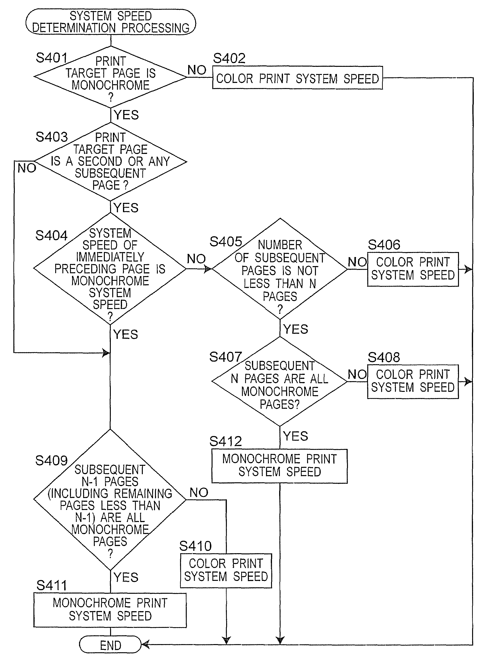
Image forming apparatus having monochrome and color print modes and a plurality of system speeds
a technology of monochrome and color print modes and system speeds, applied in the field of image forming apparatuses, can solve the problems of increasing the time taken for this switchover as a loss time, and achieve the effect of reducing loss time and reducing print speed
- Summary
- Abstract
- Description
- Claims
- Application Information
AI Technical Summary
Benefits of technology
Problems solved by technology
Method used
Image

Examples
Embodiment Construction
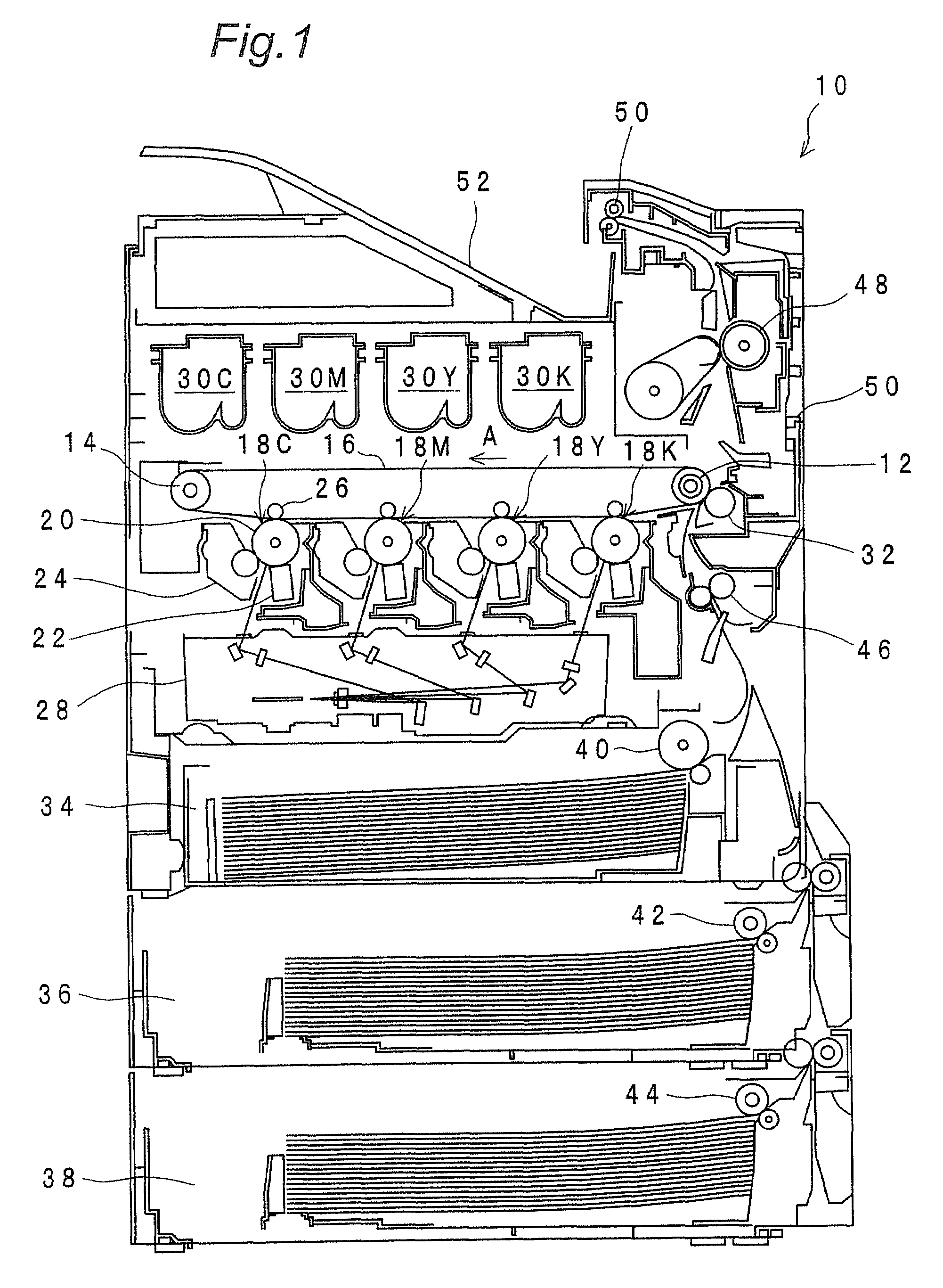
[0047]FIG. 1 is an overall structure view showing a color laser printer 10 in a most preferred embodiment of the present invention. The printer 10 has an endless film-like intermediate transfer belt 16 which is hung over two rollers 12, 14 disposed parallel at a specified distance and is rotationally driven in an arrow A direction.
[0048]Below the intermediate transfer belt 16, image forming units 18C, 18M, 18Y, 18K corresponding to four-color toners C (cyan), M (magenta), Y (yellow) and K (black) are juxtaposed. Since the respective image forming units 18C, 18M, 18Y, 18K share the same structure, their structure is described by taking the image forming unit 18C as an example.
[0049]The image forming unit 18C has a dram-like photoreceptor 20 which is rotationally driven in the state of being in contact with the intermediate transfer belt 16. Around the photoreceptor 20, a charging unit 22 for uniformly charging the surface of the photoreceptor 20, a development unit 24 for developing ...
PUM
 Abstract
Description
Claims
Application Information