Vapor chamber heat sink

a heat sink and vapor chamber technology, applied in the field of heat sinks, can solve problems such as adversely affecting the operation stability of computers, and achieve the effect of improving contact area and thermal conductive speed

Inactive Publication Date: 2010-04-20
HON HAI PRECISION IND CO LTD +1
View PDF18 Cites 0 Cited by
  • Summary
  • Abstract
  • Description
  • Claims
  • Application Information

AI Technical Summary

Benefits of technology

[0005]According to a preferred embodiment of the present invention, a vapor chamber heat sink attached to a heat-generating electronic component includes a base defining an opening therein. A plurality of fins is mounted on the base. A heat pipe thermally connects the electronic component and the fins. The heat pipe comprises a plate-type lower portion contacting a bottom surface of the base and a bottom surface of the fins. The lower portion of the heat pipe also overlays a top surface of the electronic component. A plate-type upper portion parallel to the lower portion contacts a top surface of the fins, and a connecting portion interconnecting two opposite ends of the lower and upper portions. The heat pipe is configured in such a manner so as to enhance contact area and thermal conductive speed between the heat pipe and the electronic component and between the heat pipe and the fins.

Problems solved by technology

Such heat can adversely affect the operational stability of the computers.

Method used


Image

  • Vapor chamber heat sink
  • Vapor chamber heat sink
  • Vapor chamber heat sink

Examples


Embodiment Construction

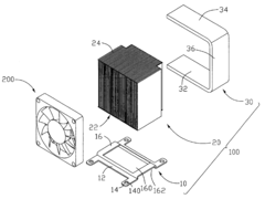
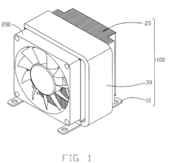
[0017]FIG. 1 shows a vapor chamber heat sink 100 in accordance with a preferred embodiment of the present invention. The heat sink 100 is configured for cooling a heat-generating electronic component (not shown), such as, for example, an integrated circuit or a CPU chip, which emits heat. The heat sink 100 dissipates heat from the heat-generating electronic component. The heat sink 100 comprises a base 10, a plurality of fins 20 mounted on the base 10 and a U-shaped, flat-type heat pipe 30 thermally connecting the heat-generating electronic component and the fins 20. A fan 200 is mounted on a front side of the fins 20 to generate and direct an airflow through channels formed between the fins 20. The channels extend along a front-to-rear direction.

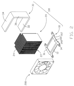
[0018]Referring to FIG. 2, the heat pipe 30 is made of high thermally conductive metal material such as copper or aluminum and define therein a U-shaped chamber in which a wick structure (not shown) and working fluid (not shown) are prefera...


PUM


Abstract

A vapor chamber heat sink attached to a heat-generating electronic component includes a base (10) defining an opening therein. A plurality of fins (20) is mounted on the base. A heat pipe (30) thermally connects the electronic component and the fins. The heat pipe comprises a plate-type lower portion (32) contacting a bottom surface of the base and a bottom surface (22) of the fins and overlaying a top surface of the electronic component, a plate-type upper portion (34) parallel to the lower portion contacting a top surface (24) of the fins, and a connecting portion (36) interconnecting opposite two ends of the lower and upper portions. The heat pipe is configured in such a manner so as to enhance contact area and thermal conductivity between the heat pipe and the electronic component and between the heat pipe and the fins.

Description

FIELD OF THE INVENTION[0001]The present invention relates to a heat sink, and particularly to a vapor chamber heat sink having a wide contact area.DESCRIPTION OF RELATED ART[0002]A computer central processing unit (CPU) is the core controller of electrical signals in most contemporary personal computers. Continued development of CPUs has enabled them to perform more and more functions. Heat generated by the CPUs has thus increased enormously. Such heat can adversely affect the operational stability of the computers. Measures must be taken to efficiently remove the heat from the CPU. Typically, a heat sink with heat pipes having great heat conductivity is mounted on the CPU to remove heat therefrom.[0003]Referring to FIG. 9, a conventional heat sink with a heat pipe includes a plate-type base 10a, a plurality of fins 30a mounted on the base 10a and a heat pipe 20a thermally connecting the base 10a and the fins 30a. The heat pipe 20a has a round cross section and includes an evaporati...

Claims


Application Information

Patent Timeline
Patent Type & AuthorityPatents(United States)
IPC IPC(8): H05K7/20
CPCH01L23/427H01L23/467H01L2924/0002H01L2924/00
InventorPENG, XUE-WENCHEN, BINGLI, JUN-HAI
OwnerHON HAI PRECISION IND CO LTD