Method and apparatus for calibrating a sound beam-forming system

a beam-forming system and sound beam technology, applied in the field of home entertainment devices, can solve the problems of limiting the possible locations of speaker placement, inability to simply place speakers at any location in the room and still function properly, and inability to achieve the effect of maximum audio separation

Inactive Publication Date: 2010-09-28
CIRRUS LOGIC INC
View PDF26 Cites 50 Cited by
  • Summary
  • Abstract
  • Description
  • Claims
  • Application Information

AI Technical Summary

Benefits of technology

[0018]In other embodiments of the invention, generally provided as selectable operating modes in conjunction with the above-described surround beam-forming, calibration of beam-forming types other than surround beam-forming may be employed. In one such “night mode” calibration technique and operating mode, a beam-forming system is calibrated to form a beam as narrow as possible at a specific l

Problems solved by technology

However, proper installation of surround channel speakers can be costly and undesirable in many home environments.
Since the surround channel audio sources are generated for a particular location of the speakers, they cannot be simply placed at any location in the room and still function properly.
It is desirable to position the surround speakers in such a way that the surround sound is diffuse, often limiting possible locations for speaker placement.
However, such systems do not provide surround sound performance approaching that of actual surround sound implementations.
However, such arrays are costly, as separate drivers must be provided for

Method used


Image

  • Method and apparatus for calibrating a sound beam-forming system
  • Method and apparatus for calibrating a sound beam-forming system
  • Method and apparatus for calibrating a sound beam-forming system

Examples


Embodiment Construction

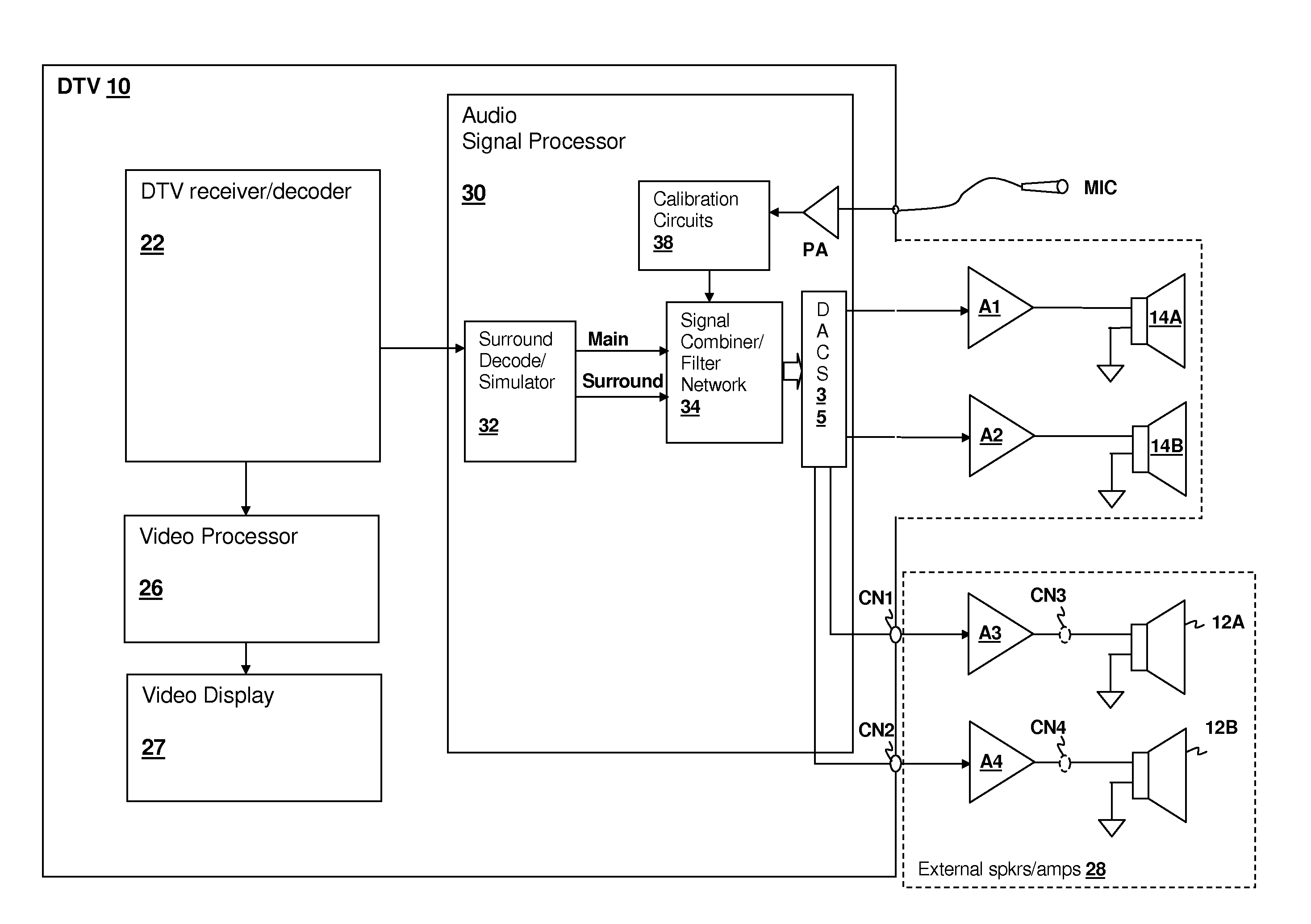
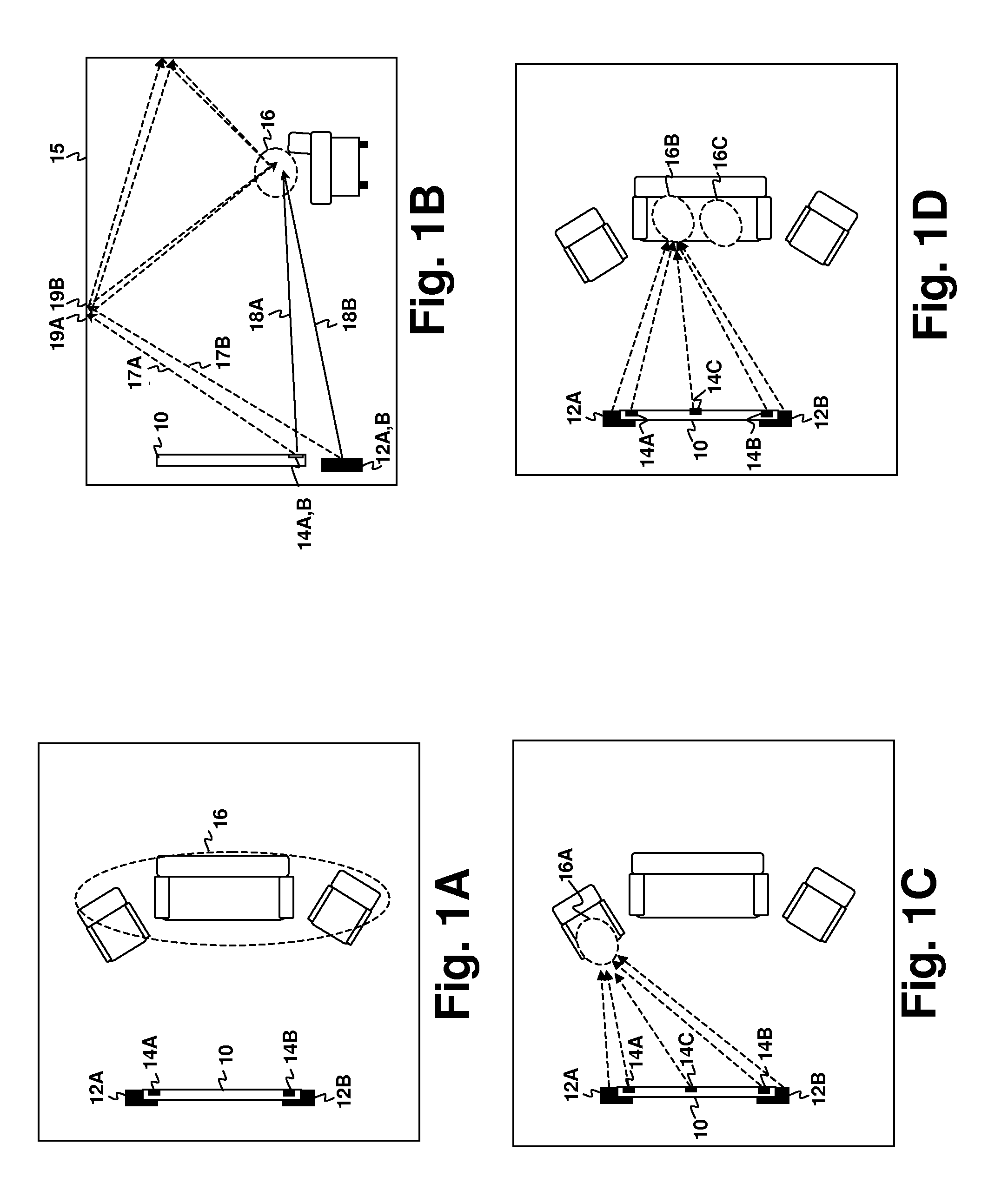
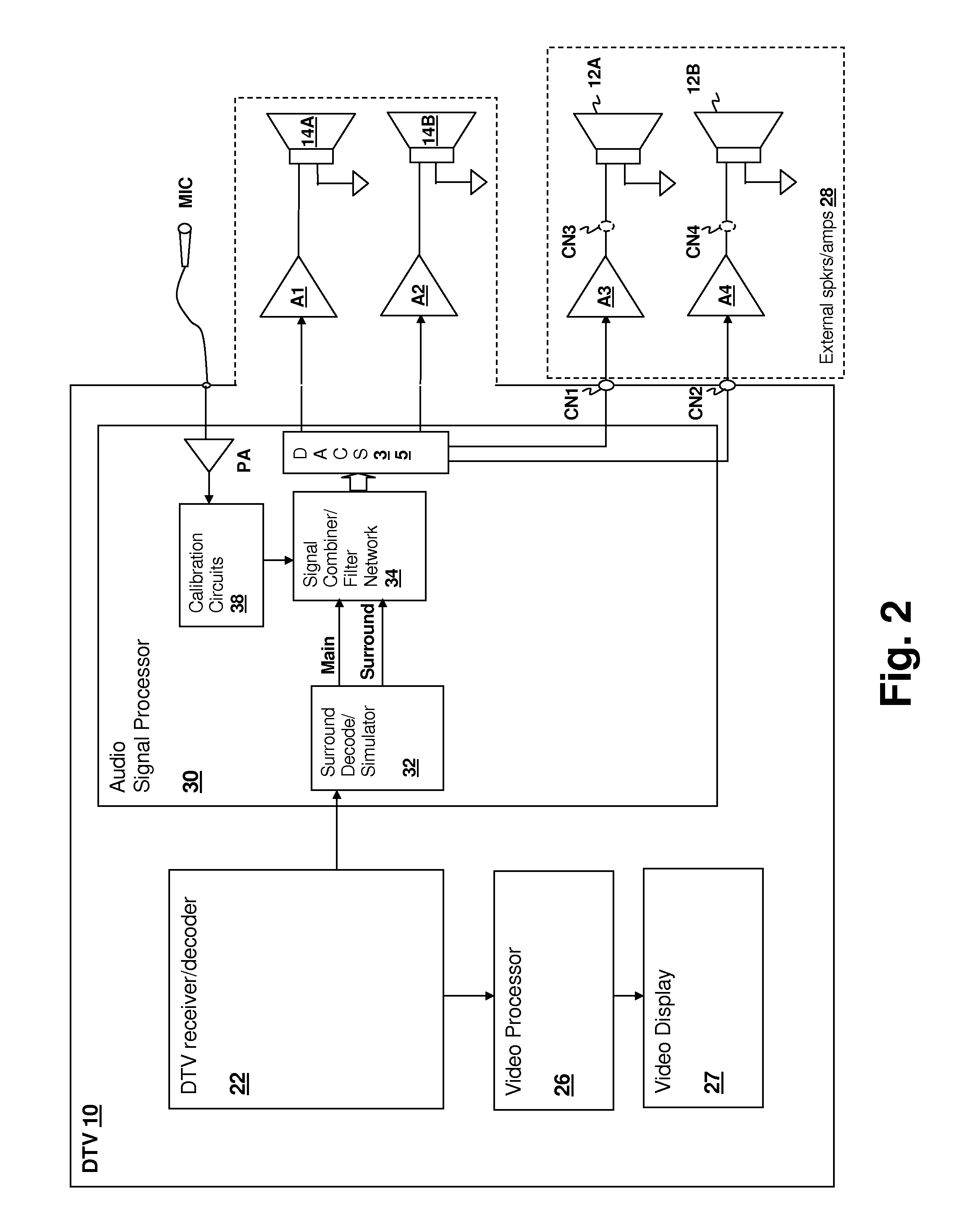
[0036]The present invention encompasses systems and methods for calibrating audio systems that include beam-forming capabilities. The system may be a device such as a video device having speakers included for the rendering of audio content, such as a DTV or computer monitor, may be an audio-only device, such as a stereo system having internal speakers, or beam-forming capabilities may be incorporated within the speaker cabinets attached to an ordinary audio or video device. In a surround simulation mode, the surround channel signal(s) are provided via beam-forming that produces reflections via one or more beams directed away from the listener. The beam(s) are formed by a phase-aligned combination of an internal and an external speaker and calibrated by a method according to an embodiment of the present invention using a test signal and a microphone. Special beam-forming modes provide an isolated listening location for night-time viewing (“Night Mode”) or for simultaneous viewing of ...


PUM


Abstract

A method and apparatus system for calibrating a sound beam-forming system provides calibration of low cost alternatives to present array beam-forming systems. A test signal is supplied to multiple speaker drivers and is detected from a microphone signal supplied from a microphone positioned at a listening position. A signal relationship between surround channel information supplied to the multiple speaker drivers is adjusted in conformity with the detected signal so that the surround channel information is substantially attenuated along a direct path toward the listening position. The result is that the surround channel information is propagated in a directivity pattern having at least one primary lobe directed away from the listening position so that the surround channel information is diffused by reflection before reaching the listening position. The signal relationship may be controlled by multiple digital filters that maximize late vs. early response of the surround channel information.

Description

CROSS-REFERENCE TO RELATED PATENT APPLICATIONS[0001]The present application is a Continuation-in-Part of U.S. patent application Ser. No. 11 / 383,125, entitled “METHOD AND SYSTEM FOR SURROUND SOUND BEAM-FORMING USING THE OVERLAPPING PORTION OF DRIVER FREQUENCY RANGES”, filed on May 12, 2006 now U.S. Pat. No. 7,545,946 by the same Inventor and assigned to the same Assignee. The specification of the above-referenced U.S. patent application and its parent U.S. patent application Ser. No. 11 / 380,840, entitled “METHOD AND SYSTEM FOR SOUND BEAM-FORMING USING INTERNAL DEVICE SPEAKERS IN CONJUNCTION WITH EXTERNAL SPEAKERS”, filed on Apr. 28, 2006, are incorporated herein by reference. The present application is also related to U.S. patent application Ser. No. 11 / 421,381, entitled “METHOD AND SYSTEM FOR SURROUND SOUND BEAM-FORMING USING VERTICALLY DISPLACED DRIVERS” and Ser. No. 11 / 425,976, entitled “RECONFIGURABLE AUDIO-VIDEO SURROUND SOUND RECEIVER (AVR) AND METHOD”, by the same inventor an...

Claims


Application Information

Patent Timeline
IPC IPC(8): H04R5/02
CPCH04S7/301H04R3/12H04R2201/401H04R2430/20
Inventor MELANSON, JOHN L.
Owner CIRRUS LOGIC INC
Why Eureka
Try Eureka