Induction hardening method and jig used in induction hardening process

a technology of induction hardening and jig, which is applied in the direction of heat treatment equipment, manufacturing tools, furnaces, etc., can solve the problems of reducing the degree of precision in dimensions, the roundness of a ring-shaped part may be inferior to the roundness before the process is performed, and the satisfactory solution has not yet been found. to prevent the loss of roundness

Inactive Publication Date: 2011-10-11
AISIN AW CO LTD
View PDF5 Cites 0 Cited by
  • Summary
  • Abstract
  • Description
  • Claims
  • Application Information

AI Technical Summary

Benefits of technology

[0010]During the induction hardening process, the outer circumferential surface of the outer ring portion is first inductively heated and therefore thermally expands. Consequently, the inner circumferential surface of the outer ring portion and the pressing surface naturally move away from each other. However, because a biasing force is applied to the pressing member in such a direction that the pressing member approaches the steel member, i.e., the pressing member moves forward relative to the steel member, at least in an initial stage where the degree of the thermal expansion of the outer ring portion is small, the pressing surface remains abutted against the inner circumferential side of the outer ring portion, whereby a force that enhances the degree of roundness is transferred from the pressing surface to the inner circumferential surface of the outer ring portion. Consequently, it is possible to maintain the roundness during the heating process.
[0012]Subsequently, in the induction hardening process, the steel member is rapidly cooled using, for example, water and the outer ring portion contracts due to the cooling. Consequently, even in the case where the pressing surface and the inner circumferential surface of the outer ring portion separate from each other during the heating process, at the end of the process they return to the state in which they abut against each other. Thus, these two elements press against each other with a high force when the steel member contracts due to the cooling. Because the inner circumferential surface of the outer ring portion is strongly pressed against the pressing surface, the degree of roundness is maintained.

Problems solved by technology

The induction hardening process works extremely well as a method for enhancing the strength of the steel members, but also has a possibility of lowering the degree of precision in the dimensions.
For example, after an induction hardening process is performed, the roundness of a ring-shaped part may be inferior to the roundness before the process is performed.
However, a satisfactory solution had not yet been found.
It is, however, not possible to use the disclosed jig to improve the roundness when an induction hardening process is performed on the outer circumferential surface of a part.

Method used


Image

  • Induction hardening method and jig used in induction hardening process
  • Induction hardening method and jig used in induction hardening process
  • Induction hardening method and jig used in induction hardening process

Examples


first embodiment

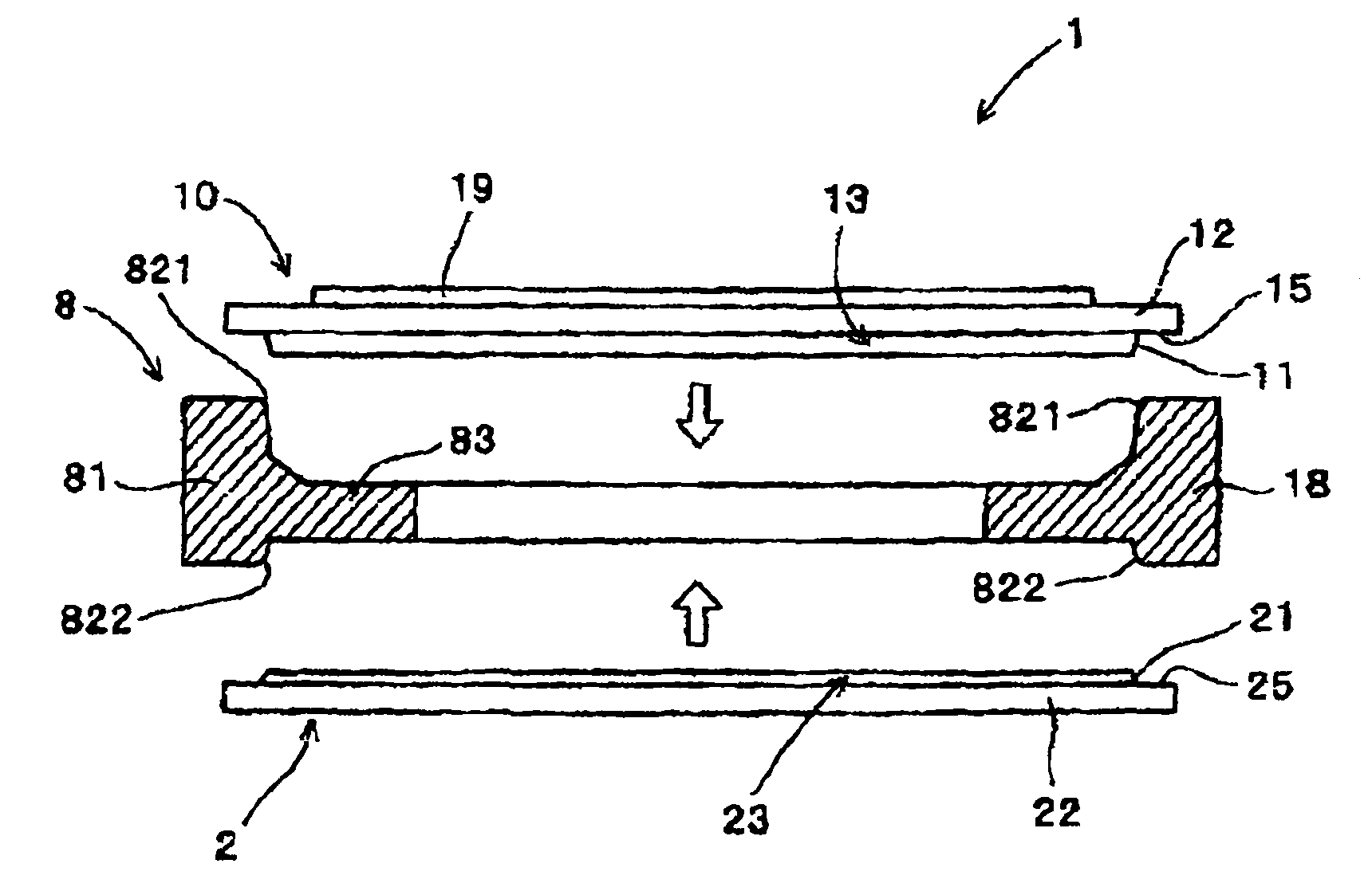
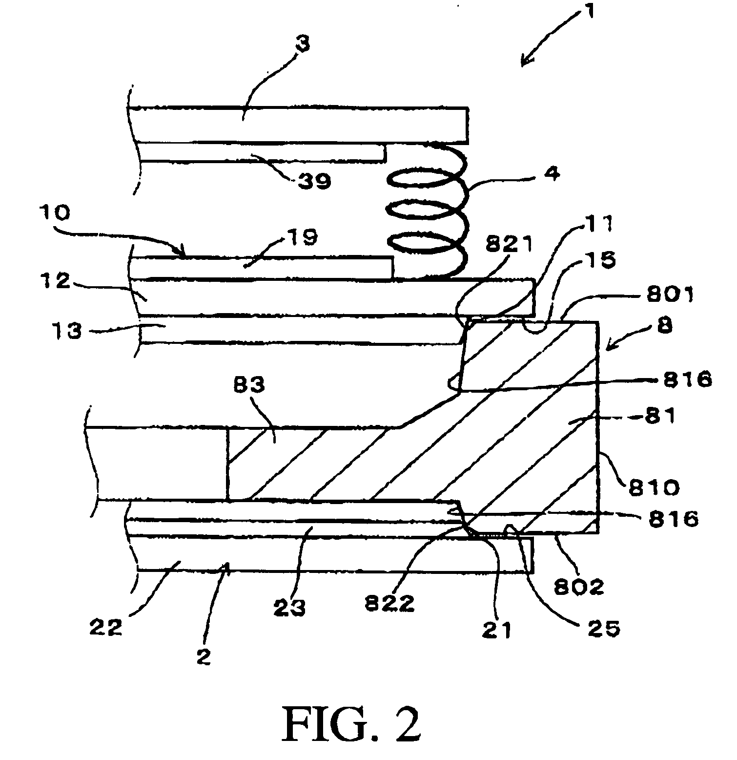
[0049]An induction hardening method and a jig to be used in a hardening process according to an embodiment of the present invention will be explained with reference to FIG. 1 through FIG. 7.

[0050]According to the first embodiment, as shown in FIGS. 7A and 7B, an induction hardening is performed on an outer circumferential surface 810 of an outer ring portion 81 of a steel member 8. The outer ring is substantially in the shape of a circular tube. To be more specific, the steel member 8 is a differential ring gear that is a component of an automatic transmission (A / T) in an automobile. The steel member 8 has, on the outer circumferential surface 810 of the outer ring portion 81, a tooth portion including a large number of teeth 811. On the inner circumference side of the outer ring portion 81 is an inner annular portion 83 that has a smaller axial thickness than the outer ring portion 81. The inner annular portion 83 extends from the axial middle of the inner circumferential surface 8...

second embodiment

[0063]According to a second embodiment of the present invention, as shown in FIGS. 8A to 8D, the first pressing member 10 and the second pressing member 2 (not shown in FIGS. 8A to 8D) are arranged in a setting stage before initiating induction hardening, with the first pressing member 10 having a corner (angle) portion 119 on pressing surface 11 of the first pressing member 10 abutting the inner circumferential surface 816 of the outer ring portion 81, and the second pressing member being configured in the same manner as the first pressing member 10.

[0064]The second embodiment is different from the first embodiment only in terms of the positions at which the pressing surfaces 11 and 21 of the first and the second pressing members 10 and 2 abut against the inner circumferential side of the outer ring portion 81. Thus, according to the second embodiment, it is possible to achieve the same effect as in the first embodiment.

third embodiment

[0065]According to a third embodiment of the present invention, as shown in FIGS. 9A to 9D, the first pressing member 10 and the second pressing member 2 are arranged in a setting stage before an induction hardening processing is performed, the first pressing member 10 being configured so that the pressing surface 11 of the first pressing member 10 abuts against the inner circumferential surface 816 of the outer ring portion 81, and the second pressing member being configured in the same manner as the first pressing member 10.

[0066]Again, the third embodiment is different from the first embodiment only in terms of the positions at which the pressing surfaces 11 and 21 of the first and the second pressing members 10 and 2 abut against the inner circumferential side of the outer ring portion 81. Thus, according to the third embodiment, it is possible to achieve the same effect as in the first embodiment.

Experimental

[0067]In order to quantitatively evaluate the advantageous effect of t...


PUM

PropertyMeasurementUnit
shapeaaaaaaaaaa
diameteraaaaaaaaaa
axial forceaaaaaaaaaa

Abstract

The present invention provides a method for induction hardening of a steel member having an outer ring portion and, more specifically, for induction hardening of an outer circumferential surface of the outer ring portion. The method uses two pressing members, each of which includes a flat basal surface and a projecting portion projecting therefrom. Each of the projecting portions has a cross-section in the shape of a perfect circle. Also, the projecting portions have, on the outer circumferences thereof, respective pressing surfaces. While gaps are maintained between axial end faces of the outer ring portion and the basal surfaces of the pressing members, the pressing members are pressed against the outer ring portion so that the pressing surfaces each abut against the inner circumference side of the outer ring portion. While a biasing force is applied to the pressing members, the induction hardening process is applied to the outer circumferential surface. During the induction hardening process, the pressing members are moved toward each other until the basal surfaces abut against respective axial end faces of the outer ring portion.

Description

TECHNICAL FIELD[0001]The present invention relates to a method for improving the dimensional precision in an induction hardening process applied to a ring-shaped steel member.BACKGROUND ART[0002]Ring-shaped steel members such as gears having teeth on their outer circumferential surface are popularly used as parts in various types of mechanical apparatus. For example, a large number of gears including differential ring gears and counter gears are used in automatic transmissions in automobiles.[0003]Generally, such ring-shaped steel members are required to have high-strength characteristics. An example of a method for imparting high-strength characteristics is an induction hardening process applied to the outer circumferential surfaces of the steel members.[0004]The induction hardening process works extremely well as a method for enhancing the strength of the steel members, but also has a possibility of lowering the degree of precision in the dimensions. For example, after an inductio...

Claims


Application Information

Patent Timeline
Patent Type & Authority Patents(United States)
IPC IPC(8): C21D8/10C21D8/00C21D9/32
CPCC21D1/10C21D9/32Y02P10/25
Inventor OHBAYASHI, KOUJIOKADA, KAZUAKI
Owner AISIN AW CO LTD
Why Eureka
Try Eureka