Charging interface for rechargeable devices

a charging interface and rechargeable technology, applied in the direction of electrical equipment, basic electric elements, coupling device connections, etc., can solve the problems of difficult or impossible to accidentally use the wrong charger, damage the connection between the device portion and the charging interface, and damage the device portion of the charging interface, so as to reduce the stress on the solder connection, the charging interface is particularly durable, and the resistance to twisting or bending.

Active Publication Date: 2011-12-06
SPIN MASTER LTD
View PDF18 Cites 1 Cited by
  • Summary
  • Abstract
  • Description
  • Claims
  • Application Information

AI Technical Summary

Benefits of technology

[0008]The present invention provides a charging interface for rechargeable devices which is more durable and easier to use than charging interfaces presently available in the prior art.
[0009]The present charging interface comprises a female socket and a corresponding single male plug, which is a circuit board and which slidably and electrically interconnects with the female socket in at least two orientations. One of the male plug and the female socket makes electrical contact with the master circuit board and the other of the male plug and the female socket is adapted to be electrically connected to a power source. The present charging interface is particularly durable as there are no delicate male prongs which could be bent or broken if the male part of the plug were improperly inserted in the female slot.
[0010]In at least one embodiment, the male plug is formed from a piece of circuit board substrate and fits snugly into a provided slot on the master circuit board, where it may then be soldered into place. This acts to stabilize the male plug and to render the male plug particularly resistant to twisting or bending at the male plug / master circuit board interface, thereby greatly reducing the stress on the solder connections which maintain electrical contact between the male plug and the master circuit board. Alternatively, the male plug may be integrally formed in the master circuit board.
[0011]Furthermore, the male plug of the present charging interface is non-directional as it has at least two surfaces which each have positive and negative poles in the same electrical configuration. Therefore, each surface will interact correctly with the positive and negative poles in the female socket, and therefore any orientation in which the male plug can be inserted into the female socket will provide an appropriate electrical connection. This makes the present charging interface easier to use than other prior art plugs currently available.

Problems solved by technology

For many rechargeable devices, the electrical connection between the rechargeable device and the power source is unique to the device, such that connecting a rechargeable device with a charger not intended for use with that device can cause damage to the device.
In that case, it is important for the charging interface to be designed so that it is difficult or impossible to accidentally use the wrong charger when attempting to recharge the device.
Plugging and unplugging the rechargeable device from its battery charger can damage the connection between the device portion of the charging interface and the circuit board it is attached to within the device, as the device portion of the charging interface is generally soldered to the circuit board and soldering material can be brittle when stressed.
Once these soldered connections are cracked or otherwise damaged, electrical contact may be lost.
Furthermore, many prior art charging interfaces have delicate male prongs which fit into corresponding female slots.
These male prongs can be bent or otherwise misshaped or even broken when the male prongs are incorrectly inserted in the female slots, resulting in an inoperable charging interface.
Furthermore, if the male prongs are inserted incorrectly into the female slots, an incorrect electrical connection can be made, which could cause the interface to be inoperable, or even damage the device or cause injury to the user.

Method used


Image

  • Charging interface for rechargeable devices
  • Charging interface for rechargeable devices
  • Charging interface for rechargeable devices

Examples


Embodiment Construction

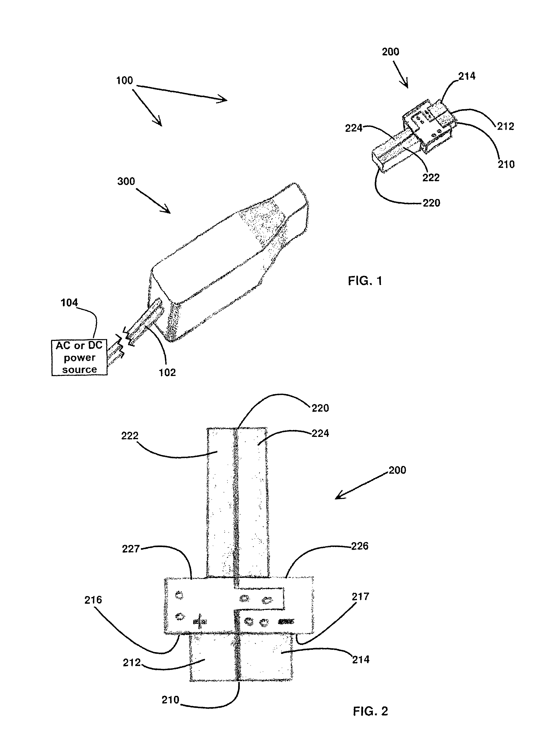
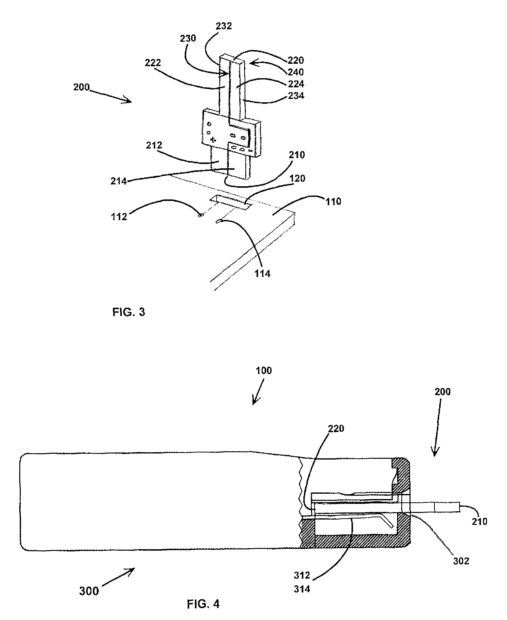
[0022]With reference to FIG. 1, in at least one embodiment the charging interface 100 of the present invention comprises a male plug 200 adapted to slidably interconnect with female socket 300. It will be apparent to the skilled person that the external housing of the female socket 300 may have any convenient shape, provided that the female socket interconnects with the male plug. Female socket 300 has a power cord 102 which can be further connected to an AC or a DC power source 104.

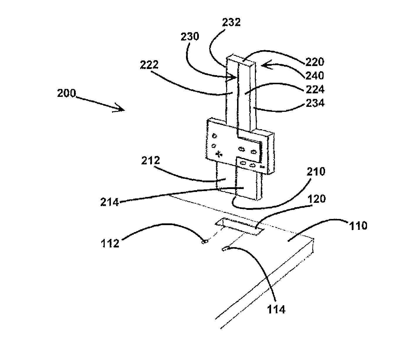
[0023]In at least one embodiment, male plug 200 is formed from standard circuit board substrate, however other materials suitable for use in a circuit board are also contemplated. Male plug 200 has a first end 210 and a second end 220. First end 210 is preferably wider than second end 220, however other configurations are contemplated.

[0024]With reference to FIGS. 2 and 3, in at least one embodiment first end 210 is narrower than the widest part of male plug 200. This creates two first shoulders 216, 217...


PUM


Abstract

A novel charging interface for rechargeable devices is disclosed herein. The present charging interface has a male plug, formed from circuit board material, which electrically and slidably interconnects with a female socket in at least two orientations. The female socket has electrically conductive biasing means which retain the male plug within the female socket. The charging interface provides electrical contact between the master circuit board of a rechargeable device and a power source.

Description

FIELD OF THE INVENTION[0001]The present invention relates to charging interfaces for rechargeable devices.BACKGROUND OF THE INVENTION[0002]Rechargeable devices are extremely popular and quite commonplace. Laptops, remotely controlled toys and cellular telephones, among other devices, all require regular recharging, and typically this involves connecting the rechargeable device to a charger in order to recharge the device's internal batteries. Chargers can contain either an AC / DC converter so that they can connect directly to an AC power source, or have an internal DC power source (such as replaceable batteries).[0003]The connection between a rechargeable device and a charger, or charging interface, typically consists of a male plug and a female socket which slidably interconnect. Each of the male plug and the female socket may be located either on the device itself or on the charger. Regardless of orientation, the device side of the charging interface is often mounted on or otherwis...

Claims


Application Information

Patent Timeline
Patent Type & Authority Patents(United States)
IPC IPC(8): H01R13/62H01R24/58
CPCH01R12/721
Inventor MAK, PAUL
Owner SPIN MASTER LTD
Why Eureka
Try Eureka