Fluid pump

a technology of fluid pump and control rod, which is applied in the direction of liquid fuel engine, machine/engine, positive displacement liquid engine, etc., can solve the problems of prior art pump number, friction between the connection and sliding friction between the piston and the control rod

Active Publication Date: 2012-04-24
BRP US
View PDF20 Cites 4 Cited by
  • Summary
  • Abstract
  • Description
  • Claims
  • Application Information

AI Technical Summary

Benefits of technology

The pump effectively delivers lubricant to multiple locations in a sequential manner, ensuring consistent lubrication and reducing the quantity of lubricant supplied to each location, thereby enhancing the effectiveness of lubrication in internal combustion engines.

Problems solved by technology

In addition, the connection between the piston and the control rod (known as the “wrist pin”) is subjected to sliding friction as the angle between the piston and the control rod changes throughout the engine cycle.
However, prior art pumps have a number of drawbacks.
These check valves are susceptible to sticking at cold temperatures, resulting in irregular or insufficient supply of lubricant.
Pumping lubricant to eight places simultaneously reduces the quantity of lubricant that can be supplied to each location, and thereby reduces the effectiveness of the lubrication.

Method used


Image

  • Fluid pump
  • Fluid pump
  • Fluid pump

Examples


first embodiment

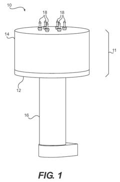
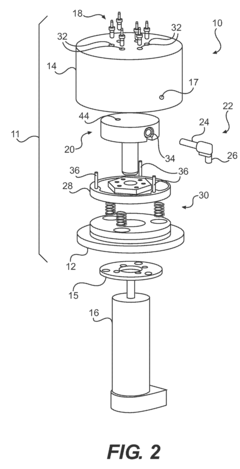
[0038]Referring generally to FIGS. 1 and 2, a pump 10 in accordance with the present invention will be described.

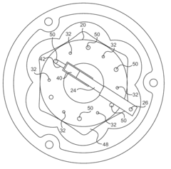
[0039]The pump 10 includes a housing 11 composed of a base plate 12 and a cover 14. The pump 10 is driven by an electric motor 16 via an adapter plate 15 (seen in FIG. 2) that is mounted to the base plate 12 via fasteners (not shown). The pump 10 may alternatively be driven by the crankshaft of an engine (not shown), or any other suitable source of power. Lubricant (not shown) enters the housing 11 via an aperture 17 (seen in FIG. 2) in the lateral wall of the cover 14 and fills the interior of the housing 11. Referring to FIG. 2, a rotor 20 is disposed inside the housing 11 such that it is free to rotate when driven by the motor 16. The rotor 20 houses a piston 22 consisting of a piston body 24 and a piston follower 26 (best seen in FIG. 4). The piston body 24 reciprocates within a bushing 34 to pump lubricant through the housing outlets 32 in the cover 14, as will be di...

second embodiment

[0050]Referring now to FIGS. 7A and 7B, a pump 110 will be described according to the invention. A number of components of the pump 10 of FIG. 1, such as the base plate 12, the motor 16, the springs 30 and the pins 36, have corresponding components in the pump 110 that perform a similar function. These components of the pump 110 are not shown in FIG. 7 and will not be discussed in detail.

[0051]The pump 110 includes a housing (not shown) composed of a base plate and a cover 114. The pump 110 is driven in the same manner as the pump 10 of FIG. 2. Lubricant (not shown) enters the housing via the aperture 117 and fills the interior of the housing in the same manner as the pump 10 of FIG. 1. The cover 114 has housing outlets 132 and 133 and hose connectors 118 and 119 that function similarly to the housing outlets 32 and hose connectors 18 of FIG. 2. The inlet plate 128 has housing inlets 150 and 151 that function similarly to the housing inlets 150 of FIG. 2. As the rotor 120 rotates wi...

third embodiment

[0058]Referring now to FIG. 8, a pump 210 will be described according to the invention. A number of components of the pump 10 of FIG. 1, such as the base plate 12, the motor 16, the springs 30 and the pins 36, have corresponding components in the pump 210 that perform a similar function. These components of the pump 210 are not shown in FIG. 7 and will not be discussed in detail.

[0059]The pump 210 includes a housing (not shown) composed of a base plate (not shown) and a cover 214. The pump 210 is driven in the same manner as the pump 10 of FIG. 2. Lubricant (not shown) enters the housing via an axial channel 217 in the rotor 220 and fills the six housing inlet channels 250 on the inside of the cover 214. The cover 214 has housing outlets 232 that function similarly to the housing outlets 32 of FIG. 2. The rotor 220 functions similarly to the rotor 20 of FIG. 2. As the rotor 220 rotates within the housing, the respective piston followers 226 of the pistons 222 sequentially abut again...


PUM


Abstract

A pump is disclosed, having a pumping chamber in the rotor. The rotor is rotatable between first, second, third and fourth positions. When the rotor is in the first position, an inlet cam assembly displaces a piston to draw fluid into the pumping chamber via a first housing inlet. When the rotor is in the second position, an outlet cam assembly displaces the piston to expel fluid out of the pumping chamber via a first housing outlet. When the rotor is in the third position, the inlet cam lobe assembly displaces the piston to draw fluid into the pumping chamber via a second housing inlet. When the rotor is in the fourth position, the outlet cam assembly displaces the piston to expel fluid out of the pumping chamber via a second housing outlet. A method of pumping fluid is also disclosed.

Description

CROSS REFERENCE[0001]The present application claims priority from U.S. Provisional Patent Application No. 60 / 976,178 filed Sep. 28, 2007, entitled FLUID PUMP, which is incorporated herein by reference.FIELD OF THE INVENTION[0002]The present invention relates to a method and apparatus for pumping fluids.BACKGROUND OF THE INVENTION[0003]Internal combustion engines have many moving parts, and a number of these parts slide against each other with very tight tolerances. As such, these parts require lubrication to allow them to slide against one another and prevent the parts from becoming damaged.[0004]Lubrication of the pistons of the engine is particularly important. As the pistons reciprocate in the cylinders as many as several thousand times per minute, they slide against the cylinder walls. In addition, the connection between the piston and the control rod (known as the “wrist pin”) is subjected to sliding friction as the angle between the piston and the control rod changes throughou...

Claims


Application Information

Patent Timeline
Patent Type & AuthorityPatents(United States)
IPC IPC(8): F04B37/00
CPCF03C1/013F04B1/1071F04C9/005
InventorHUNT, DEVLINFEUERSTEIN, JOHNURBANIK, TONY
OwnerBRP US