Electrophoretic display device, electronic device, and drive method for an electrophoretic display panel

a display panel and electrophoretic technology, applied in the direction of electric digital data processing, instruments, computing, etc., can solve the problems of electrolysis of electrodes and eventual separation, and achieve the effect of improving reliability

Active Publication Date: 2012-05-08
SEIKO EPSON CORP
View PDF14 Cites 4 Cited by
  • Summary
  • Abstract
  • Description
  • Claims
  • Application Information

AI Technical Summary

Benefits of technology

[0011]An electrophoretic display device, an electronic device, and a control method for an electrophoretic display panel according to the present invention improve reliability by assuring DC balance.
[0015]To segments (or pixels) that are updated from an intermediate color to an intermediate color in this aspect of the invention, the amount of second pulses applied is substantially equal to the sum of the applied first pulses and the applied third pulses. As a result, if the first pulses, second pulses, and third pulses are integrated on the time base, the result is substantially 0. The invention can therefore assure DC balance at least in the segments (or pixels) that are updated from an intermediate color to an intermediate color.
[0023]Furthermore, when segments (or pixels) of the electrophoretic display panel according to this aspect of the invention are updated from the first color or second color to an intermediate color, third pulses of opposite polarity to the second pulse are applied in the same amount as the applied second pulses. As a result, if the second pulses and third pulses are integrated on the time base, the result is substantially 0. The invention can therefore also assure DC balance in the segments (or pixels) that are updated from the first color or second color to an intermediate color.
[0027]This aspect of the invention can reduce the application of first pulses because the first pulses are first applied in the direction requiring the fewest pulses to change all segments (or pixels) to be updated from an intermediate color to an intermediate color to the first color or the second color. As a result, the current consumption of the electrophoretic display device can be reduced.
[0033]This aspect of the invention applies the same amount of first pulses when applying a first pulse to overwrite the first color to the first color, to change the second color to the first color, and to change an intermediate color to the first color. The same amount of first pulses are also applied when applying a first pulse to change the first color to the second color, to overwrite the second color to the second color, and to change an intermediate color to the second color. This aspect of the invention enables further simplifying the configuration of the electrophoretic display device.

Problems solved by technology

A problem, however, is that when the electrophoretic display device is used for a long time, the electric field applied between the electrodes of the electrophoretic display panel becomes biased (producing a DC component), potentially resulting in electrolysis of the electrodes and eventual separation.

Method used


Image

  • Electrophoretic display device, electronic device, and drive method for an electrophoretic display panel
  • Electrophoretic display device, electronic device, and drive method for an electrophoretic display panel
  • Electrophoretic display device, electronic device, and drive method for an electrophoretic display panel

Examples


Embodiment Construction

[0055]Preferred embodiments of the present invention are described below with reference to the accompanying figures. It will be obvious to one with ordinary skill in the related art that the embodiments described below do not unduly limit the content of the invention described in the accompanying claims, and all components and parts of the following embodiments are not essential elements of the invention.

[0056]1. Electrophoretic display device and drive method for an electrophoretic display panel

[0057]* Electrophoretic Display Panel Configuration

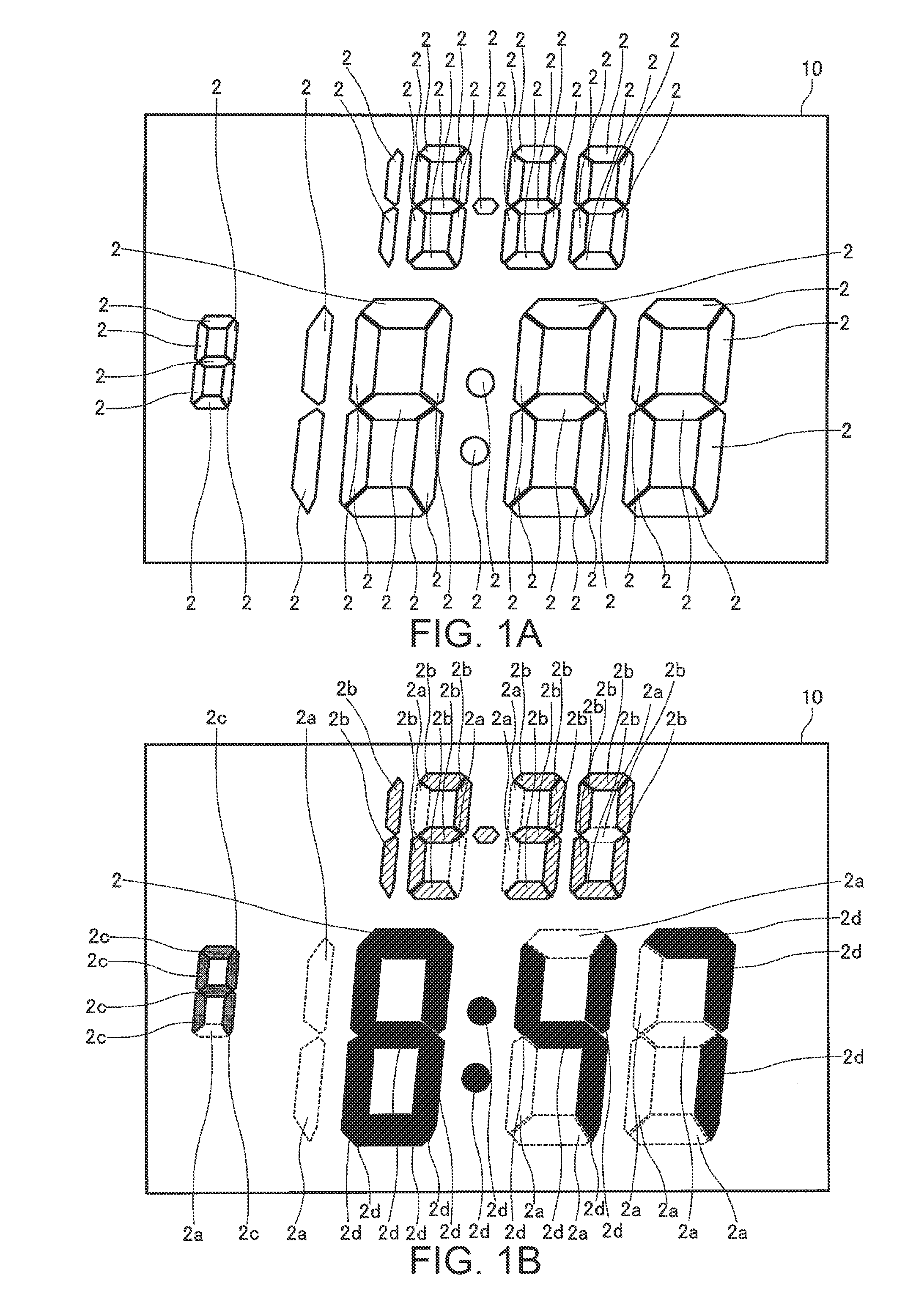
[0058]FIG. 1A is a schematic plan view of an electrophoretic display panel according to a preferred embodiment of the invention. The electrophoretic display panel 10 according to this embodiment of the invention is, for example, a display panel for displaying time information by means of plural segments 2 that can be driven to display the time. The segments 2 are configured so that each segment 2 can display a plurality of colors.

[0059]For e...


PUM


Abstract

An electrophoretic display device comprises an electrophoretic display panel having drive electrodes, a common electrode, and electrophoretic particles inbetween. The panel can update the display color of each display unit correlated to a particular drive electrode according to a voltage applied between that drive electrode and the common electrode. A drive control unit applies such voltage and also has components that determine for each display unit the current display color and selectively apply specifically configured first, second and third pulses between the common and drive electrodes of display units to effect color change.

Description

CROSS-REFERENCE TO RELATED APPLICATION(S)[0001]Japanese Patent application No. 2009-061157 is hereby incorporated by reference in its entirety. This application is also related to U.S. application Ser. No. 12 / 721,178, filed on Mar. 10, 2010.BACKGROUND[0002]1. Field of Invention[0003]The present invention relates to an electrophoretic display device, to an electronic device, and to a drive method for an electrophoretic display panel.[0004]2. Description of Related Art[0005]Electronic paper, flexible display devices, and other types of new electronic display media offering some of the characteristics of hard-copy media such as paper media have been developed. Some of the features of such electronic display media include better readability and less eye fatigue than CRT, LCD, and other display device technologies that are commonly used with modern personal computers, the ability to bend, and excellent portability.[0006]Such electronic display media include electrophoretic display device...

Claims


Application Information

Patent Timeline
Patent Type & Authority Patents(United States)
IPC IPC(8): G09G3/34G02B26/00
CPCG09G3/344G09G3/2018G09G2310/0254G09G2320/0204G09G2320/0257
Inventor KANBAYASHI, HATSUKITANABE, TAKUYA
Owner SEIKO EPSON CORP
Why Eureka
Try Eureka