Adjustable character stamp

a character stamp and adjustment technology, applied in the field of stamps, can solve the problems of difficult stamping of workpieces which are not simply flat and/or strong materials, and the cost of such machines includes not only the stamps themselves, but also the cost of the drive structure to move the stamps up to the workpiece, etc., to achieve the effect of convenient operation and control

Inactive Publication Date: 2012-09-25
CARL DAN PEDDINGHAUS
View PDF14 Cites 0 Cited by
  • Summary
  • Abstract
  • Description
  • Claims
  • Application Information

AI Technical Summary

Benefits of technology

[0011]The present invention provides a novel, improved stamp for imprinting or stamping characters in a workpiece, and is particularly advantageously suited to stamp selected characters in workpieces. This is accomplished with a compact structure which may be easily operated and controlled with minimal addition of parts, particularly when used in conjunction with a punch module.
[0012]In one aspect of the present invention, an adjustable stamp for stamping characters on a workpiece is provided, including a base plate with a platen, a plurality of stamps each having a raised character on one side, a stamp holder, and a support securing the stamps to the holder in an array. The supported stamps have one side facing a stamping direction and the opposite side facing a retract direction opposite the stamping direction. The support allows limited free motion of the stamps relative to each other in the stamping and retract directions, and is mounted to the base plate for movement in a plane substantially perpendicular to the stamping direction to selectively position a selected one of the stamps over the platen with the platen facing the opposite side of the selected one of the stamps. The base plate and the workpiece may be pressed together, whereby the raised character of the selected one of the stamps is stamped into the workpiece by the platen pressing against the opposite side of the one stamp, and the free motion of the other stamps prevents their raised characters from being stamped into the workpiece.
[0016]In yet another form of this aspect of the invention, the support is mounted to the base plate by first and second tracks extending in first and second axial directions substantially perpendicular to each other, the first and second axial directions also being substantially perpendicular to the stamping and retracting directions. In a further form, the second track is carried by the first track, the support is carried by the second track, a first drive selectively positions the second track along the first axial direction relative to the base plate, and a second drive selectively positions the support along the second axial direction relative to the first track, whereby the supported stamps are positioned relative to the platen so that the stamp having the raised character to be stamped is selectively positioned over the platen. In still further forms, (a) the first and second tracks are slide bearings, and (b) the first and second drives are multi-position air cylinders. In yet another further form, (c) the stamp holder is a character holding plate having an opening therethrough, and the support is a plurality of dowel pins surrounding the character holding plate opening, and a plurality of elastic O-rings looped over the dowel pins on opposite sides of the character holding plate opening to support the stamps in the opening of the character holding plate, and in a still further form the stamps include grooves between the one sides and the opposite sides, and at least some of the O-rings are received in the grooves to support the stamps, and the elasticity of the O-rings allows the limited free motion.
[0019]In one form of this aspect of the invention, the stamp holder is a character holding plate having an opening therethrough, and the support includes a plurality of dowel pins surrounding the character holding plate opening, and a plurality of elastic O-rings looped over the dowel pins on opposite sides of the character holding plate opening to support the stamps in the opening of the character holding plate. In further forms, (a) the character holding plate opening is substantially rectangular and the array is a generally rectangular matrix with a plurality of columns and rows in the opening, (b) one set of the O-rings extends in one ring direction between the dowels across the character holding plate opening and the remaining ones of the O-rings extend between the dowels in a second ring direction perpendicular to the first ring direction, and (c) the stamps include grooves between the one sides and the opposite sides, and at least some of the O-rings are received in the grooves to support the stamps, with the elasticity of the O-rings allows the limited free motion.

Problems solved by technology

Workpieces which are not simply flat and / or are made of strong material can be particularly difficult to stamp with desired identifying information.
Moreover, due to the difficulty of such stamping, machines separate and apart from the punching and shearing machines have often been provided to accomplish the stamping.
In either case, the cost of such machines includes not only the stamps themselves, but also the cost of the drive structure to move the stamps up to the workpiece.

Method used


Image

  • Adjustable character stamp
  • Adjustable character stamp
  • Adjustable character stamp

Examples


Embodiment Construction

[0038]While this invention is susceptible of embodiment in many different forms, this specification and the accompanying drawings disclose only one specific form as an example of the use of the invention. The invention is not intended to be limited to the embodiment so described, and the scope of the invention will be pointed out in the appended claims.

[0039]For ease of description, the apparatus operating in accordance with this invention is described in the normal (upright) operating position, and terms such as upper, lower, horizontal, etc., are used with reference to this position.

[0040]The apparatus of this invention can have certain conventional components and control mechanisms the details of which, although not fully illustrated or described, will be apparent to those having skill in the art and an understanding of the necessary functions of such components and mechanisms.

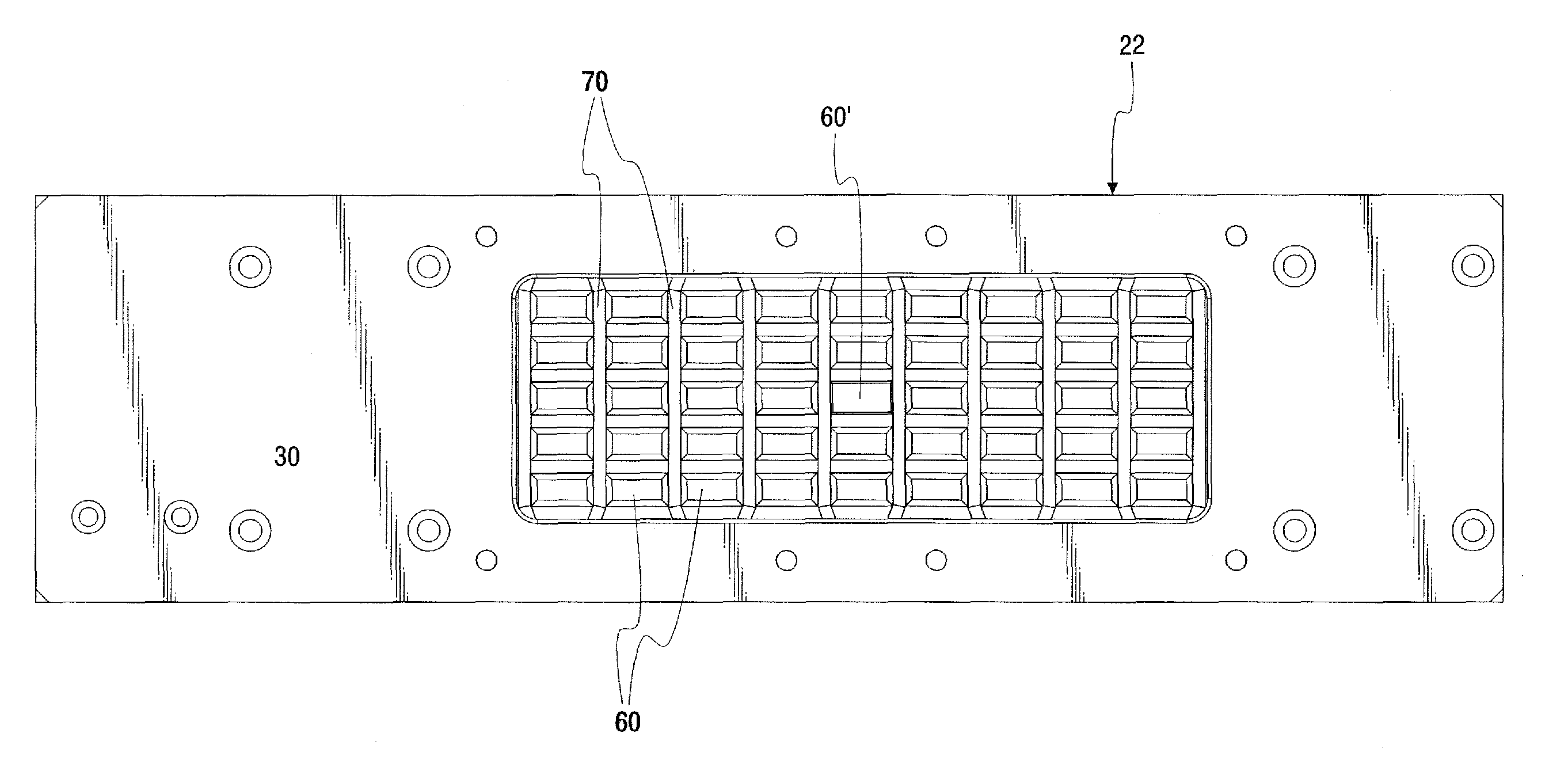
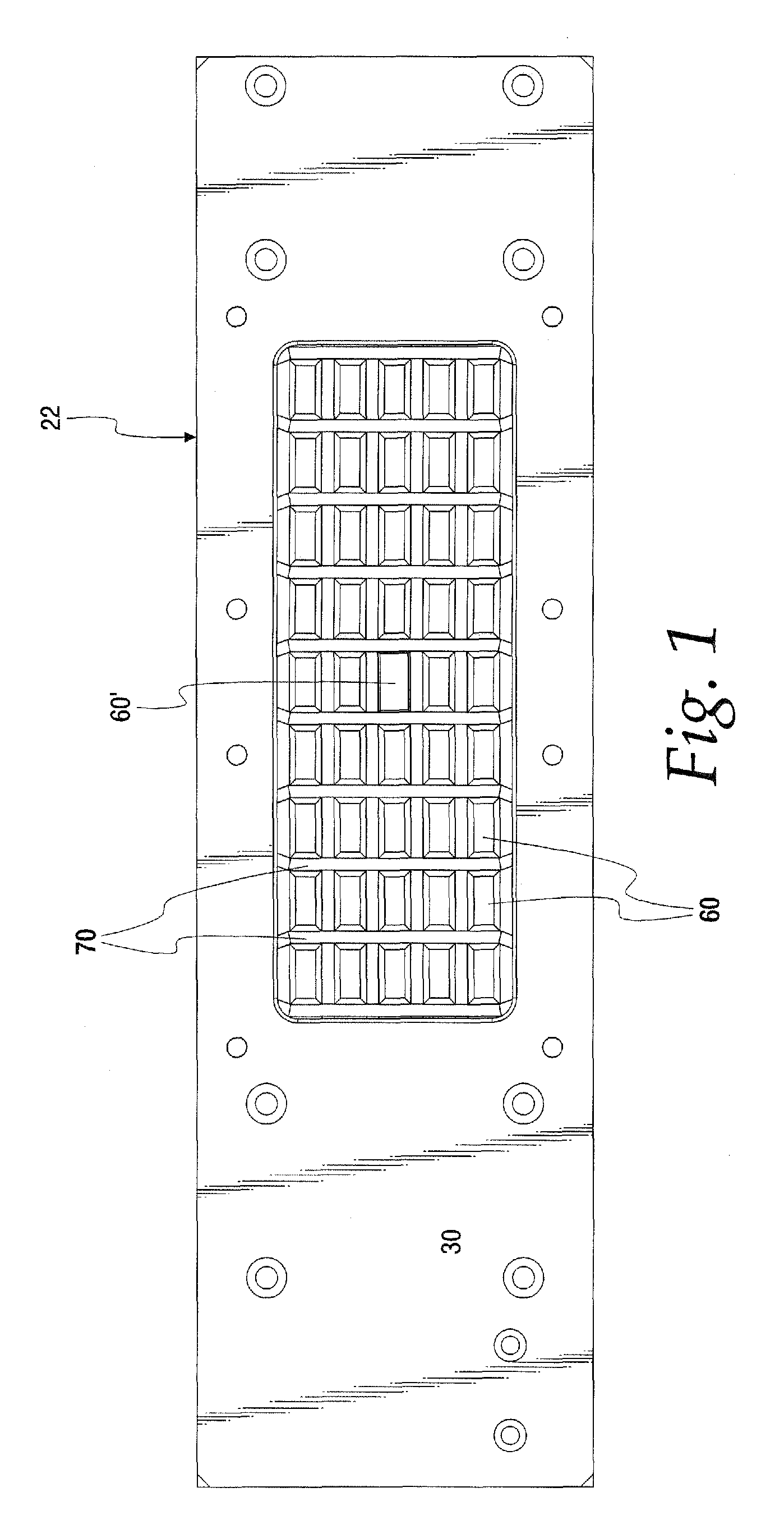
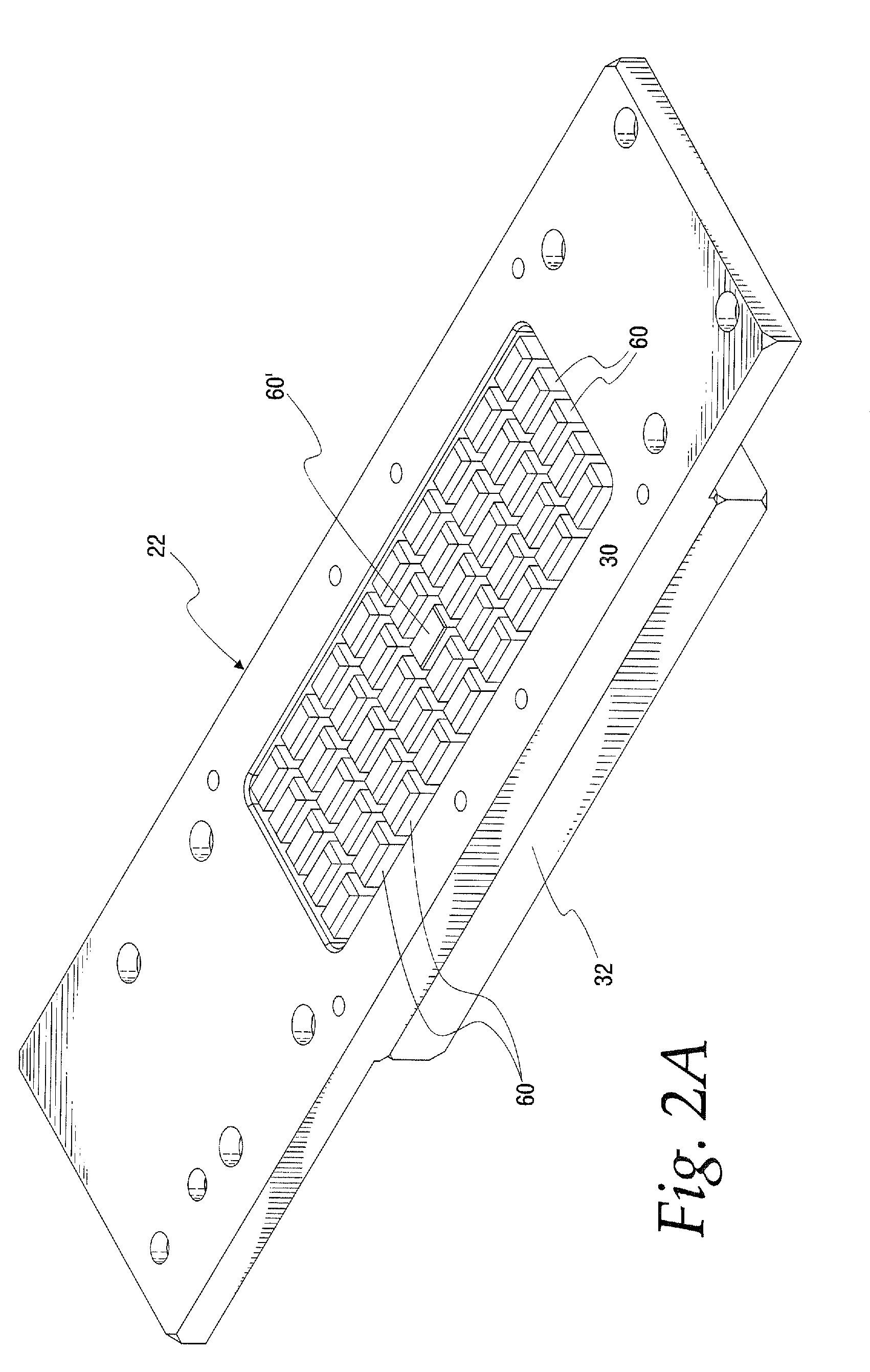
[0041]Some of the Figures illustrating the preferred embodiment of the apparatus of the present inventio...


PUM


Abstract

An adjustable stamp for stamping characters on a workpiece, including a base plate with a platen, a plurality of stamps each having a raised character on one side, a stamp holder, and a support securing the stamps to the holder in an array while allowing limited free motion of the stamps relative to each other in the stamping and retract directions. The support is mounted to the base plate for movement in a plane substantially perpendicular to the stamping direction to selectively position one of the stamps over the platen. The base plate and the workpiece may be pressed together, whereby the raised character of the one stamp is stamped into the workpiece by the platen pressing against the opposite side of the one stamp, with the free motion of the other stamps preventing their raised characters from being stamped into the workpiece.

Description

CROSS REFERENCE TO RELATED APPLICATION(S)[0001]Not applicable.STATEMENT REGARDING FEDERALLY SPONSORED RESEARCH OR DEVELOPMENT[0002]Not applicable.REFERENCE TO A MICROFICHE APPENDIX[0003]Not applicable.TECHNICAL FIELD[0004]This invention relates to a stamp for stamping characters on a workpiece, particularly on the legs of a structural angle.BACKGROUND OF THE INVENTION AND TECHNICAL PROBLEMS POSED BY THE PRIOR ART[0005]Stamping of workpieces with a variety of identifying information is required in many applications. For example, workpieces may advantageously include part identifying information stamped thereon to help to ensure that the correct part pieces are used in the correct applications and / or in the correct locations.[0006]Workpieces which are not simply flat and / or are made of strong material can be particularly difficult to stamp with desired identifying information. For example, structural angle workpieces (e.g., angle irons) may have two longitudinal members connected at r...

Claims


Application Information

Patent Timeline
Patent Type & Authority Patents(United States)
IPC IPC(8): B44B5/00
CPCB44B5/0057
Inventor MULLIKIN, JEFFREY A.
Owner CARL DAN PEDDINGHAUS
Why Eureka
Try Eureka