Structural improvement of submersible cooling pump

a submersible cooling pump and structure technology, applied in the direction of pump components, piston pumps, non-positive displacement fluid engines, etc., can solve the problems of tedious practice and take a while to observ

Active Publication Date: 2012-12-11
WANG LI CHUAN
View PDF10 Cites 71 Cited by
  • Summary
  • Abstract
  • Description
  • Claims
  • Application Information

AI Technical Summary

Benefits of technology

[0008]The primary object of the present invention is to provide a submersible cooling pump that varies in the length of its stud set as required and has better coaxial fastening stability during the actuation of the pump and a relatively longer service life by means of providing a removable support pipe that is disposed on the one side other than where the duct pipe is.
[0009]Another object of the present invention is to provide a submersible cooling pump with a motor set that is provided with, on the motor casing, a screw fastened motor cover, and, under the same casing, a fixing base fastened also by screws, so as to make inspection and servicing of the motor easy.
[0011]Further another object of the present invention is to provide a submersible cooling pump with a motor set with a motor cover on which a protecting cover is provided to serve as a dust cover effectively keeping foreign objects like chips from entering the components of the device.

Problems solved by technology

Such a submersible cooling pump has drawbacks as follows:1. Its stud set together with the impeller set being in a fixed pattern is unable to change the length to adapt to different depths of the liquid container.
So, to make such an observation requires removing the motor cover, an inconvenient and dangerous operation; besides, to determine the direction of the rotation, it must take a while of observation, somewhat tedious practice, as the indicator point is too small to make an easy determination.3. Also, in motor casing, the motor cover is provided with heat dissipating holes allowing the heat generated by the motor in its rotation to be dissipated through; but, in previous motor casings, there is no protective structure to prevent dust or chips from entering the pump which cause damages to the parts of the device.

Method used


Image

  • Structural improvement of submersible cooling pump
  • Structural improvement of submersible cooling pump
  • Structural improvement of submersible cooling pump

Examples


first embodiment

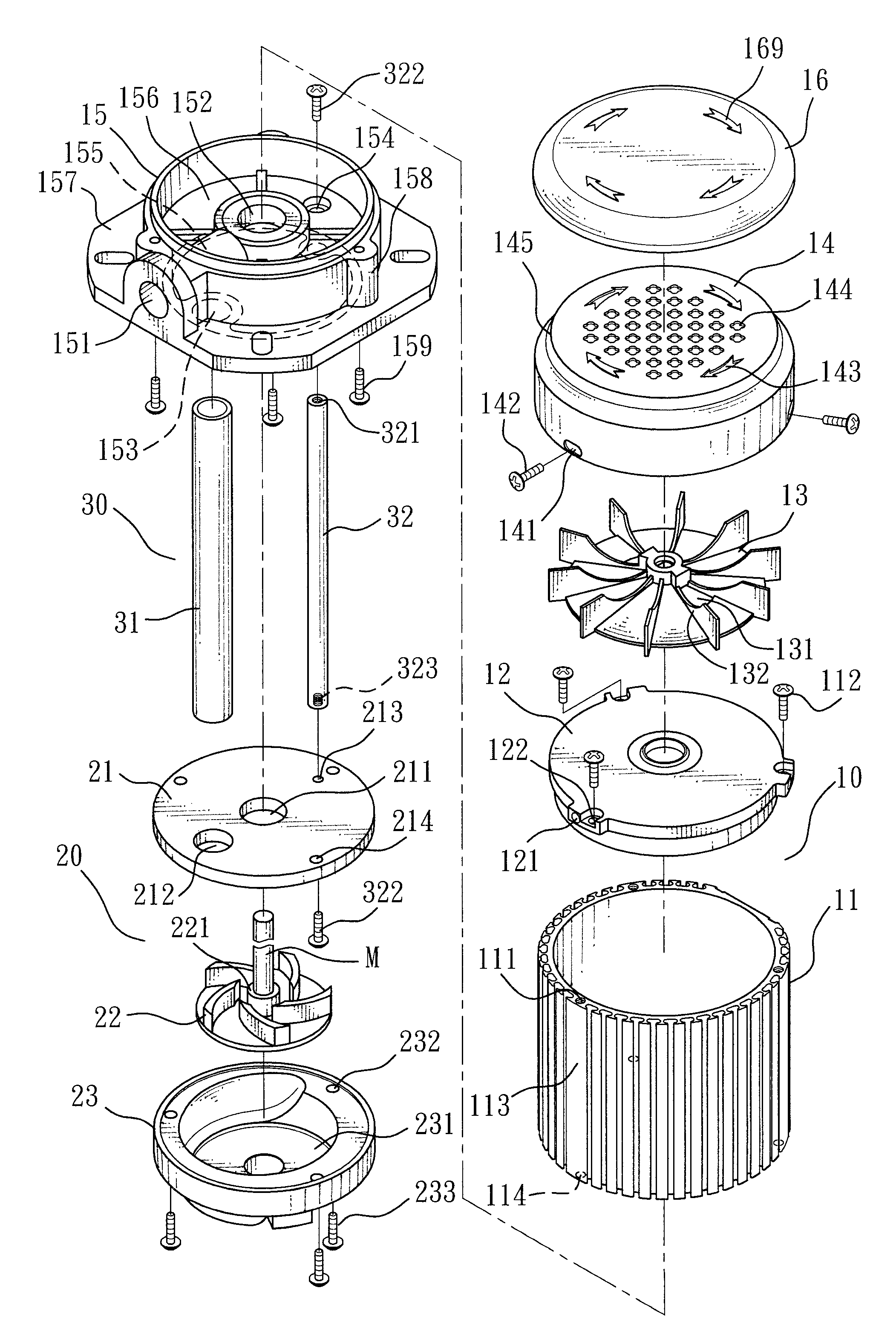
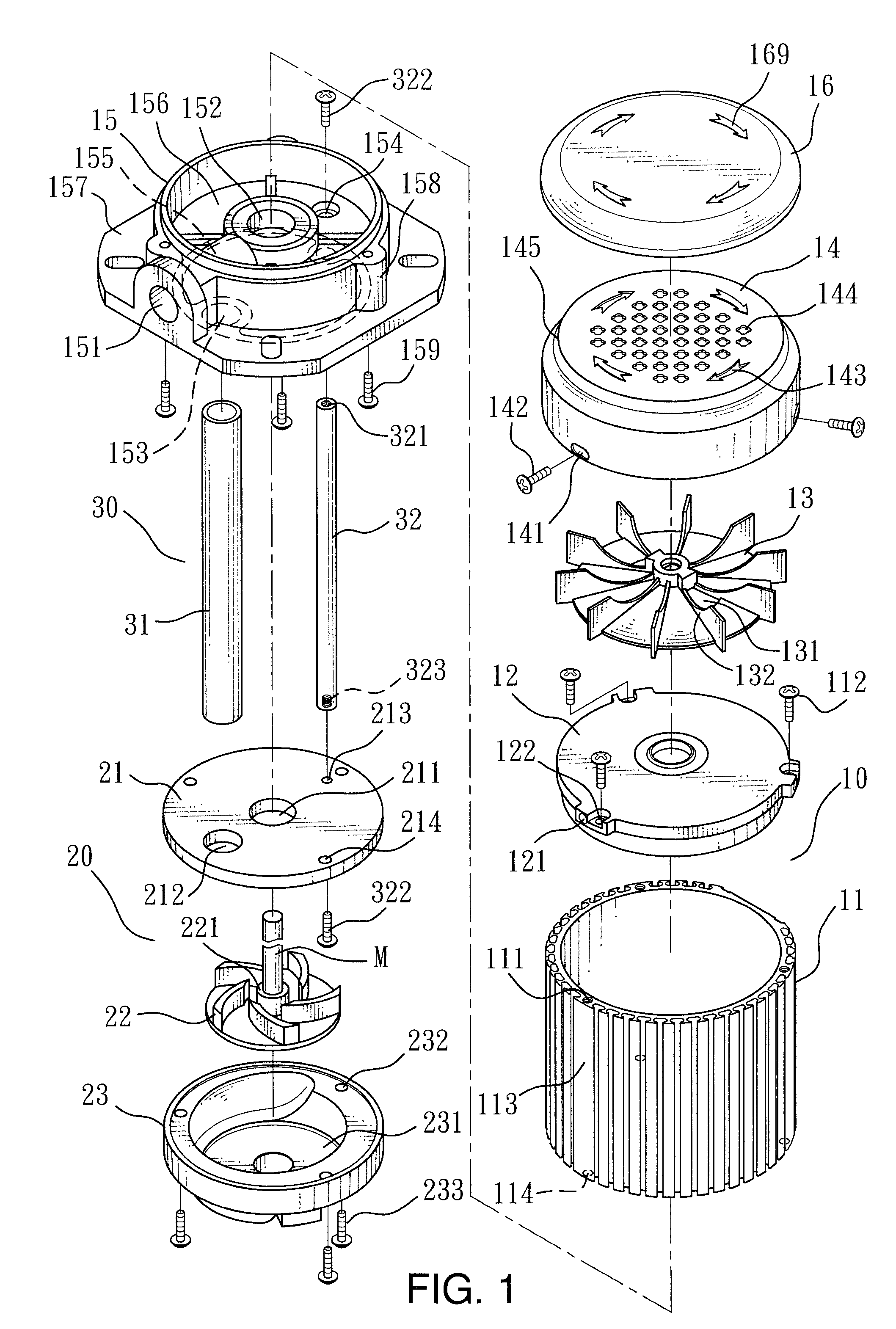
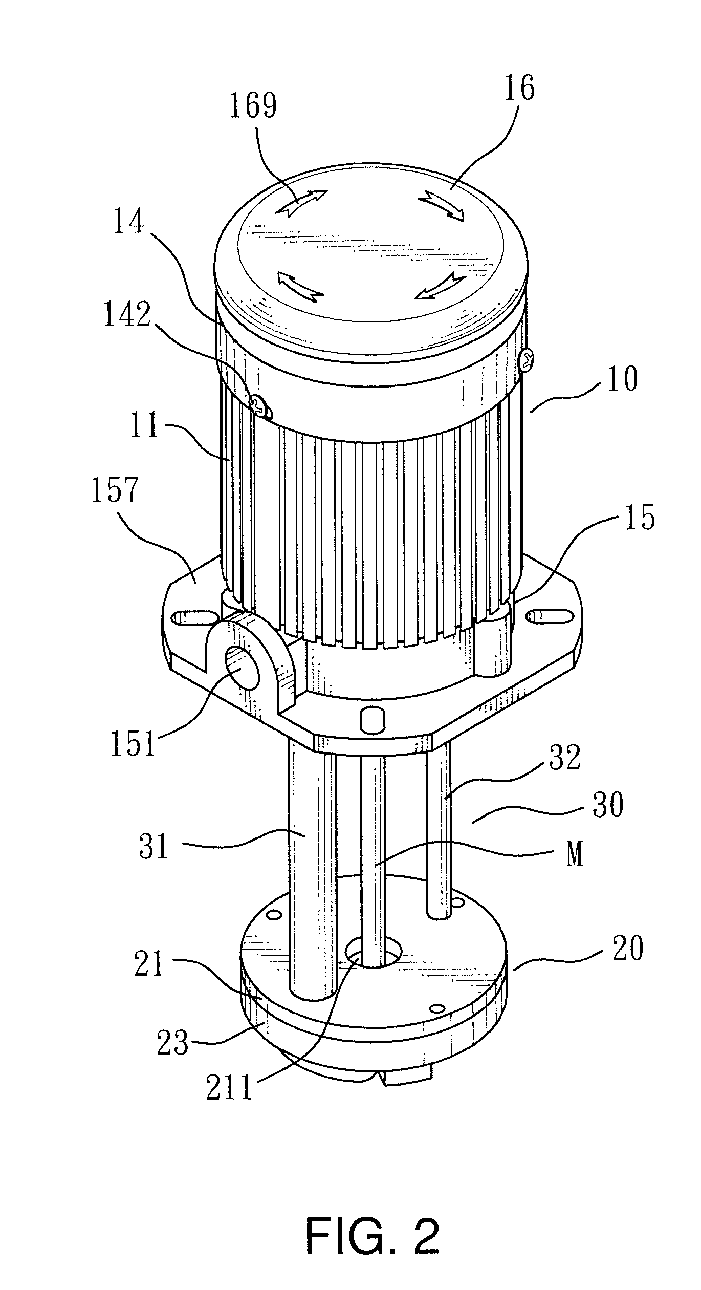
[0023]Reference is first made to FIG. 1 to FIG. 5, which show the present invention that comprises a motors set 10, an impeller set 20 and a stud set 30; wherein

[0024]said motors set 10 has a motor casing 11, which has two or more flat areas 113 and a plurality of grooves, and a plurality of screw holes 111 on the upper rim to allow the attachment of the fixing holes of a top plate 12 thereto through screws 112; a fan 13 and a motor cover 14 provided on said top plate 12, said fan 13, on which an opposite pair of orifices 131 is provided, consisting of a plurality of arc-shape guide blades 132, said motor cover 14 having through holes 141 on the side for its attachment to said top plate 12 along with screws holes 121 on the top plate 12 by screws 142, the same motor cover 14, the upper side of whose rim forms a recessed guiding surface 145, also having arrow shaped sight holes 143 and cross-shaped ventilating holes 144 densely distributed inside the imaginary circle of the sight hol...

third embodiment

[0037]Reference is now made to FIG. 10, which shows the present invention. This embodiment has the same function as that of the foregoing filter drum, yet, it further provides a lower annular groove 82 in the top surface of the top cover 81 in order for the filter drum to fit in and achieve the same effect.

[0038]All the foregoing description is given to make it clear that with the capability of changing the length of the pipes, and of enhancing the linkage between the motor set and the impeller set so as to prolong the service life, the convenience in inspecting and servicing the motor, as well as a protecting cover keeping dust and chips from entering the components of the device, the present invention possesses non-obviousness as well as utility.


PUM


Abstract

A structural improvement of submersible cooling pumps, especially a submersible cooling pump that is capable of enhancing the stability and extending service life, comprising a motor set, an impeller set and a stud set, characterized in that in said motor set, there are provided on the motor casing a top plate, disposed on which is a fan with orifices, and a motor cover having sight holes and cross-shaped ventilating holes that spreads all over the cover, disposed on top of said fan, and a protection cover with a small elastic plate provided to cloak said motor cover which is screw fastened to said motor casing; the lower end of said motor casing fits on the upper rim of the trough of a fixing base, and is fastened onto the fixing hole base of said fixing base; on said fixing base an outlet port and shaft hole are provided, and by both sides of said shaft hole an ingress of water and a positioning hole that permits the screw fastening of another element are provided; said impeller set combines and fastening an upper cover and a lower cover to accommodate a set of vanes, wherein an outlet hole is provided by one side, and a fixing hole by the other side, of an inlet hole of said upper cover; and said stud set consists of a duct pipe and a support pipe, both of equal length, of which the support pipe has female thread at each end allowing it to be screw fastened to the positioning hole of said motor set and the fixing hole of said impeller set, respectively.

Description

BACKGROUND OF THE INVENTION[0001]1. Field of the Invention[0002]The present invention relates to a structural improvement of submersible cooling pump, more specifically, a submersible cooling pump that varies in the length of its stud set as required, has better structural stability and longer service life, as well as allows the spinning direction of motor, indicated by the rotation of provided orifices, to be observed directly through sight holes on the motor cover.[0003]2. Description of the Prior Art[0004]Submersible cooling pumps structurally consist mainly of a motor set and an impeller set, wherein the impeller set is immersed in a liquid container, and a supporting stud set is provided connecting the motor set with said impeller set; when the motor set operates, its shaft drives the impeller set, whose vanes turn and introduce the liquid from outside into the impeller set through the port in an upper cover and discharge, by centrifugal force, the liquid out, through a duct pi...

Claims


Application Information

Patent Timeline
Patent Type & Authority Patents(United States)
IPC IPC(8): F04B35/04
CPCF04D29/628F04D13/08
Inventor WANG, LI-CHUAN
Owner WANG LI CHUAN
Why Eureka
Try Eureka