Image recording system, image recording apparatus, and image recording method

a recording system and image technology, applied in the field of image recording apparatus, image recording system, image recording method, can solve the problems of difficult process for separating out only the image data to be modified, two pieces of image data cannot be easily distinguished from each other, and achieve the effect of easy identification of image signals, modification and determination of image signal pairs

a recording system and image technology, applied in the field of image recording apparatus, image recording system, image recording method, can solve the problems of difficult process for separating out only the image data to be modified, two pieces of image data cannot be easily distinguished from each other, and achieve the effect of easy identification of image signals, modification and determination of image signal pairs

US8355618B2Active Publication Date: 2013-01-15PANASONIC CORP

Image

  • Image recording system, image recording apparatus, and image recording method
  • Image recording system, image recording apparatus, and image recording method
  • Image recording system, image recording apparatus, and image recording method

Examples


first embodiment

[0022]1: Configuration of Image Recording System

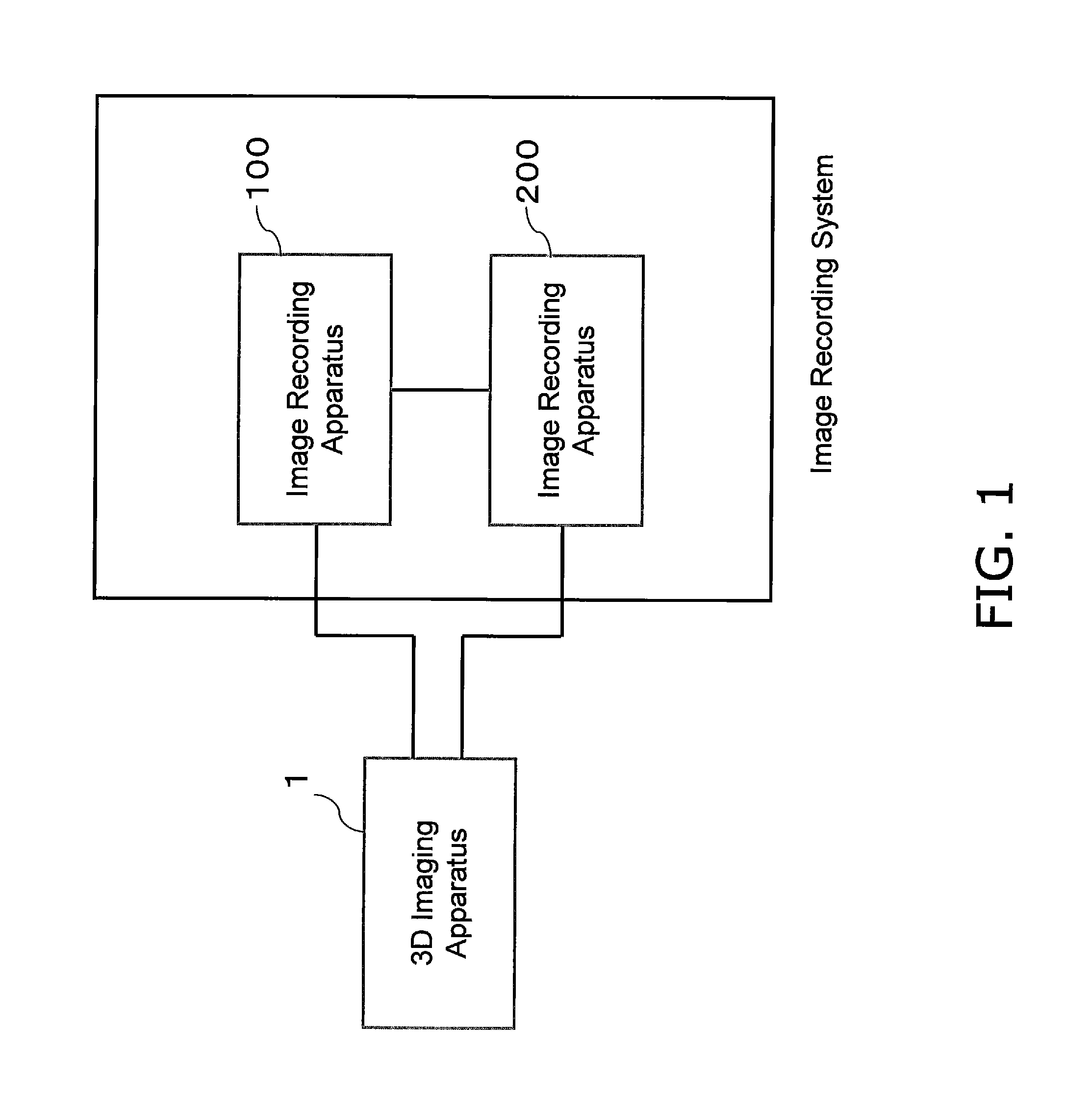
[0023]FIG. 1 is a diagram which illustrates the overall configuration of an image recording system according to a first embodiment. A 3D imaging apparatus 1 is a dual-lens imaging apparatus that outputs a left-lens image and a right-lens image that configure 3D image as individual image signals. The image recording system is configured of an image recording apparatus 100 that records the left-lens image output by the 3D imaging apparatus 1 and an image recording apparatus 200 that records the right-lens image output by the 3D imaging apparatus 1. The image recording apparatus 100 and the image recording apparatus 200 are connected via a network, and are capable of exchanging data with each other.

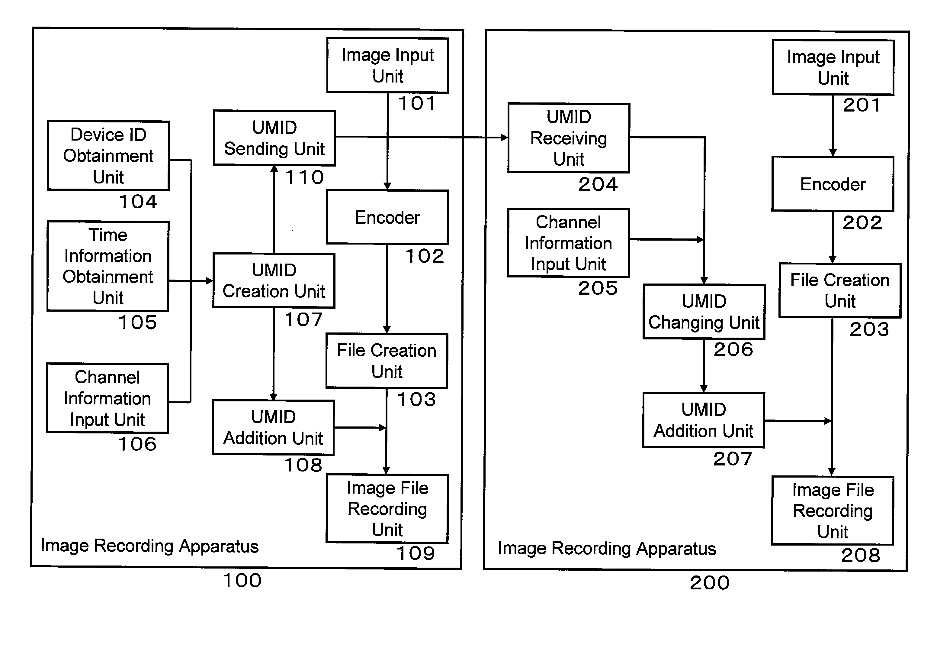
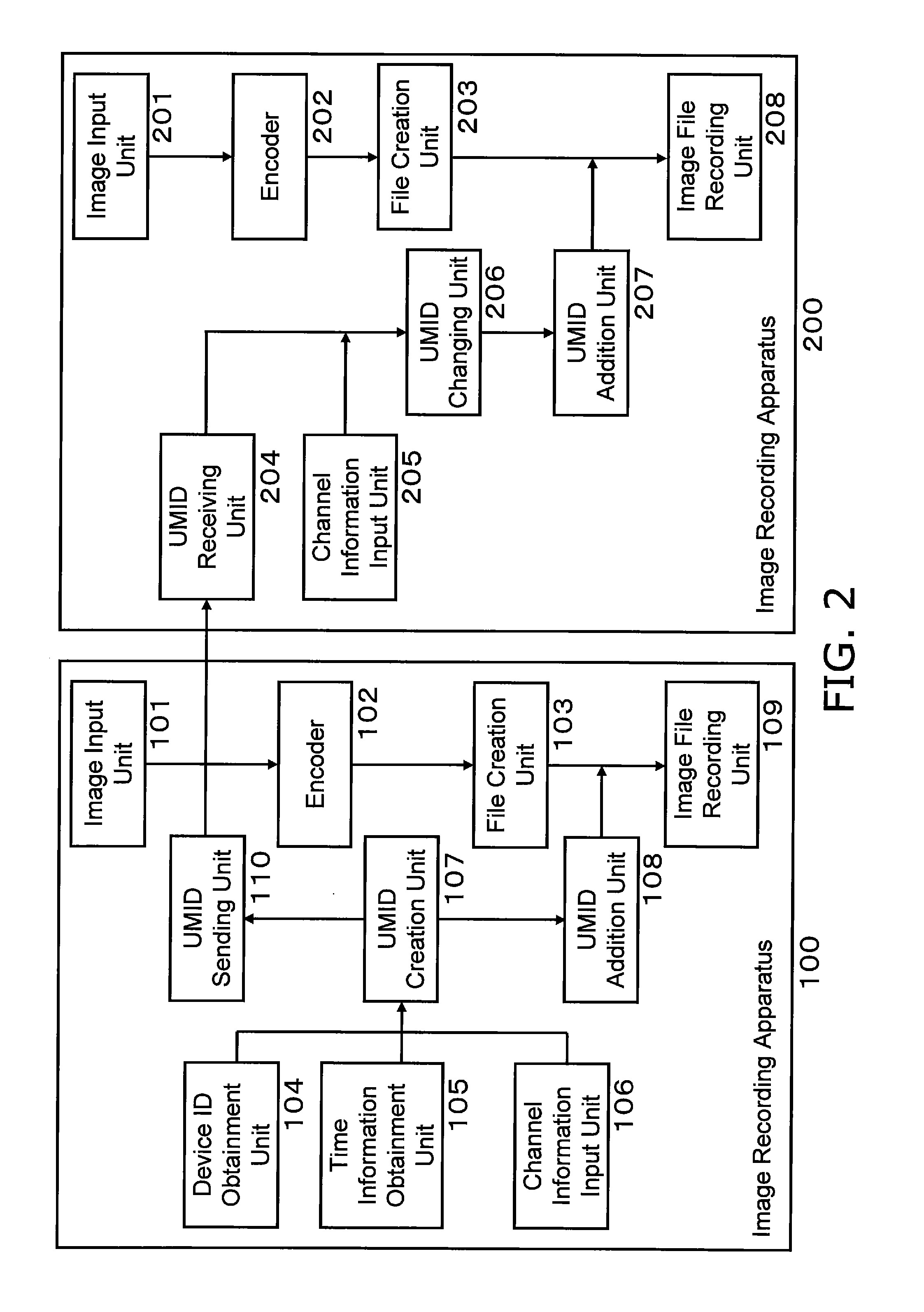
[0024]FIG. 2 is a block diagram which illustrates the configuration of the image recording apparatuses of which the image recording system is configured. The image recording apparatus 100 is configured of an image input unit 101, an encoder 102...

second embodiment

[0049]1. Configuration of Image Recording Apparatus

[0050]FIG. 3 is a block diagram which illustrates the configuration of an image recording apparatus according to a second embodiment. An image recording apparatus 300 is configured of an image input unit (L) 301, an encoder (L) 302, a file creation unit (L) 303, an image input unit (R) 304, an encoder (R) 305, a file creation unit (R) 306, a device ID obtainment unit 307, a time information obtainment unit 308, a channel information input unit 309, a UMID creation unit 310, a UMID addition unit 311, an image file recording unit (L) 312, and an image file recording unit (R) 313.

[0051]An L channel image signal is input into the image input unit (L) 301. The encoder (L) 302 encodes an image signal input into the image input unit (L) 301. The file creation unit (L) 303 creates a file (for example, an MXF file) from the data encoded by the encoder (L) 302.

[0052]An R channel image signal is input into the image input unit (R) 304. The enc...


PUM


Abstract

The image recording system is a system configured of first and second image recording apparatuses. The first image recording apparatus includes a device ID obtainment unit, a time information obtainment unit, a first channel information input unit, an identification information creation unit, a first image input unit, a first identification information addition unit, a first image recording unit, and an identification information sending unit. The second image recording apparatus includes an identification information receiving unit, a second channel information input unit, an identification information change unit, a second image input unit, a second identification information addition unit, and a second image recording unit.

Description

CROSS-REFERENCE TO RELATED APPLICATIONS[0001]This application claims priority to Japanese Patent Application No. 2010-259745, filed on Nov. 22, 2010. The entire disclosure of Japanese Patent Application No. 2010-259745 is hereby incorporated herein by reference.BACKGROUND[0002]1. Technical Field[0003]The technology disclosed herein relates to image recording apparatus, image recording system, and image recording method.[0004]2. Background Information[0005]A conventional recording apparatus adds identification information indicating the shooting angle when an image is shot from multiple angles. For example, JP-H7-250350A (called “Patent Document 1” hereinafter) discloses a recording apparatus. The recording apparatus is configured of an input unit, an encoding unit, a multiplexing unit, an identification code generating unit, and a code adding unit. The input unit is configured of an image input unit. The image input unit inputs pieces of image data obtained by shooting images from m...

Claims


Application Information

Patent Timeline
15 Jan 2013
Publication
US8355618B2
IPC
H04N9/80
CPC
H04N9/8227; H04N13/0055; H04N5/765; H04N13/189
Inventors
NAKAMURA, TAKAYUKI; OHTAKA, HIDEKI