Image display apparatus, image display method, and recording medium having image display program stored therein

a technology of image display and recording medium, which is applied in the field of image display apparatus and image display method, can solve the problem that the projector may not appropriately detect an input, and achieve the effect of increasing the luminance of a pixel

Inactive Publication Date: 2013-04-02
PGS GEOPHYSICAL AS +1
View PDF13 Cites 30 Cited by
  • Summary
  • Abstract
  • Description
  • Claims
  • Application Information

AI Technical Summary

Benefits of technology

[0025]In accordance with another embodiment, provided is a method for emitting laser light, displaying a first image on a first projection surface, and displaying a second image on a second projection surface, using an image display apparatus. The image display apparatus has a laser light source for outputting the laser light, a scanner for scanning the laser light, a light splitting element for splitting the laser light scanned by the scanner into a first laser beam directed to the first projection surface and a second laser beam directed to the second projection surface, and a photodetector for detecting the second laser beam reflected by an external object on the second projection surface. The method includes the steps of: executing processing of accepting image data and increasing luminance of a pixel in a designated region included in the accepted image data; allowing the scanner to operate at a prescribed scanning frequency and controlling output of the laser light by the laser light source based on the image data subjected to the processing and the scanning frequency; calculating a position of the external object based on a scanning position of the laser light at a light detection timing of the photodetector; and changing the second image based on the calculated position.

Problems solved by technology

Therefore, when the technique in Japanese Patent Laying-Open No. 2005-038422 is applied to a projector for performing presentation, the projector may not appropriately detect an input.

Method used


Image

  • Image display apparatus, image display method, and recording medium having image display program stored therein
  • Image display apparatus, image display method, and recording medium having image display program stored therein
  • Image display apparatus, image display method, and recording medium having image display program stored therein

Examples


first embodiment

[0045][First Embodiment]

[0046]

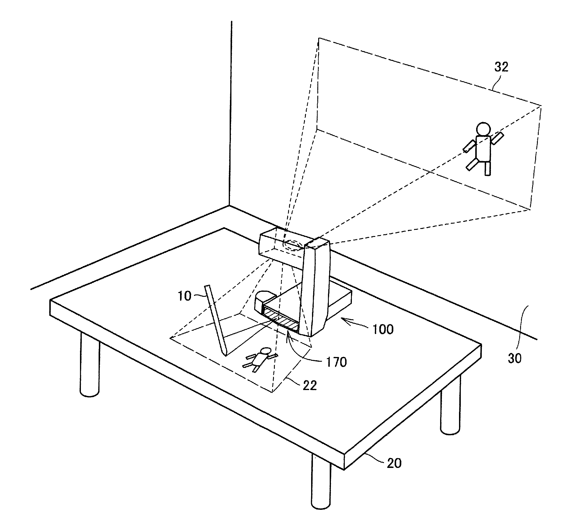
[0047]Referring to FIG. 1, a usage manner of a projector 100 in accordance with an embodiment of the present invention will be described.

[0048]In FIG. 1, projector 100 is used in such a manner to be arranged on a desk 20. Projector 100 projects a VUI (Virtual User Interface) screen image 22 in a first direction. Projector 100 also projects a main projected screen image 32 in a second direction different from the first direction.

[0049]Main projected screen image 32 is usually projected such that it can be viewed by many people. In FIG. 1, projector 100 projects main projected screen image 32 onto a wall 30. It is noted that wall 30 is an example of projection surfaces on which main projected screen 32 is projected. A screen or the like may be used in place of wall 30.

[0050]VUI screen image 22 is a screen image referred to by a user. VUI screen image 22 is usually projected in the vicinity of projector 100. In FIG. 1, projector 100 projects VUI screen ima...

second embodiment

[0188][Second Embodiment]

[0189]In the first embodiment, projector 100 for performing marker display reliably has been described. In a second embodiment, projector 100 for ensuring an operation by an icon in a projected screen image will be described.

[0190]An “icon” here refers to an image appearing in a prescribed region in a projected screen image for determining an operation instruction. An icon is preferably an image corresponding to an operation to change a screen image, such as paging. The user can operate projector 100 intuitively by performing an operation while looking at the icon on VUI screen image 22.

[0191]The hardware configuration and functional configuration of projector 100 in accordance with the second embodiment is similar to that of the first embodiment and therefore a detailed description thereof will not be repeated.

[0192]Projector 100 in accordance with the second embodiment generates a white region in an icon display region or in a region surrounding the icon d...

third embodiment

[0213][Third Embodiment]

[0214]

[0215]Projector 100 in accordance with the second embodiment generates image data 472 by CPU 140 (or image processing portion 495) in projector 100. More specifically, projector 100 can generate image data 472 by executing program 474 stored in projector 100.

[0216]In the second embodiment, projector 100 can generate image data 472 for projection, based on image data accepted from the outside. Therefore, for example, projector 100 can display a slideshow of a plurality of image files in a storage medium (such as an SD or a flash memory) attached to projector 100, in accordance with a prescribed instruction to the VUI screen image.

[0217]In contrast, projector 100# in accordance with a third embodiment does not generate image data 472 by itself. Projector 100# is used such that it is connected with external electronic equipment 1000. Projector 100# instructs electronic equipment 1000 to change image data 472 that is transmitted to projector 100# by electro...


PUM


Abstract

A projector divides and projects a single image onto two different projection surfaces and performs virtual user interface through one projection surface. The projector projects a VUI screen image on a desk and projects a main projected screen image on a wall. The projector includes a light receiving element, which is installed at a position that receives light emitted to the desk (the projection surface of the VUI screen image) and reflected (or scattered) by an object in the vicinity of the desk. The projector calculates a position of the object based on a light detection timing of the light-receiving element and a scanning position of light at each time and changes a projected image based on the calculated position. The projector displays a designated region of the VUI screen image to be brightened.

Description

BACKGROUND OF THE INVENTION[0001]1. Field of the Invention[0002]The present invention relates to an image display apparatus, an image display method, and a recording medium having an image display program stored therein for projecting images. In particular, the present invention relates to an image display apparatus, an image display method, and a recording medium having an image display program stored therein for projecting images by laser light.[0003]2. Description of the Background Art[0004]Projectors are now used in a variety of scenes to project images on projection surfaces such as screens or walls. In recent years, a wide variety of projectors have been developed.[0005]Some projectors project an image in two different directions. For example, a projector disclosed in Japanese Patent Laying-Open No. 2005-038422 displays a virtual keyboard image on a first plane and displays a user output display image on a second plane. The lower part of the virtual keyboard image is superimpo...

Claims


Application Information

Patent Timeline
Patent Type & AuthorityPatents(United States)
IPC IPC(8): G03B21/26G03B21/14H04N3/26G06F3/033H04N3/22G06F3/0346G06F3/041G06F3/0487G06F3/0488
CPCG06F1/1639G06F3/0425H04N9/3129H04N9/3147H04N9/3194
InventorNISHIGAKI, HIROSHIHIRANO, ATSUYACHIKAOKA, ATSUHIKONISHIOKA, KEN
OwnerPGS GEOPHYSICAL AS