Imaging displaying apparatus and 3-D image displaying apparatus applying the same therein

a technology of displaying apparatus and displaying apparatus, applied in the field of image displaying apparatus, can solve the problems of high cost, high price of dispersion plate for controlling dispersion/transmission or reflection/transmission, etc., and achieve the effect of increasing the contrast characteristic of the screen, low cost and high efficiency

Active Publication Date: 2013-05-14
MAXELL HLDG LTD
View PDF9 Cites 7 Cited by
  • Summary
  • Abstract
  • Description
  • Claims
  • Application Information

AI Technical Summary

Benefits of technology

[0013]According to the present invention, taking the problems mentioned above into the consideration thereof, an object thereof is to provide an image displaying apparatus, being suitable for 3-D image display, as well as, enabling to display a plural number of images of high quality at the same time, but with a low cost.
[0016]According to the present method, since it is possible to bring the size of the second light modulator unit to be small, a large-sized 3-D display apparatus can be obtained, with a low cost, even if increasing the number of the screens of 2-D image display. Further, transmission of the light through the polarizing plates a plural number of times enables to bring about other effect, i.e., increasing the contrast characteristic of the screen, greatly.
[0017]Further, between the light source and the second light modulator unit is provided a polarized light converter unit for converting the light without polarization from said light source into a desired polarization component, then it is possible to utilize the light from the light source, with high efficiency.
[0018]As was mentioned above, according to the present invention, it is possible obtain an image displaying apparatus of high picture quality, with a low cost, and also a 3-D display apparatus applying the same therein.

Problems solved by technology

However, with this 3-D image displaying apparatus, for the purpose of obtaining a large-sized 3-D image, the apparatus becomes to be large in the scale thereof (in particular, an expansion of the apparatus in the depth direction thereof), and further it is high in the cost thereof.
Moreover, the dispersion plates for controlling dispersion / transmission or reflection / transmission are very expensive in the price, in particular, when enlarging them.

Method used


Image

  • Imaging displaying apparatus and 3-D image displaying apparatus applying the same therein
  • Imaging displaying apparatus and 3-D image displaying apparatus applying the same therein
  • Imaging displaying apparatus and 3-D image displaying apparatus applying the same therein

Examples


embodiment 1

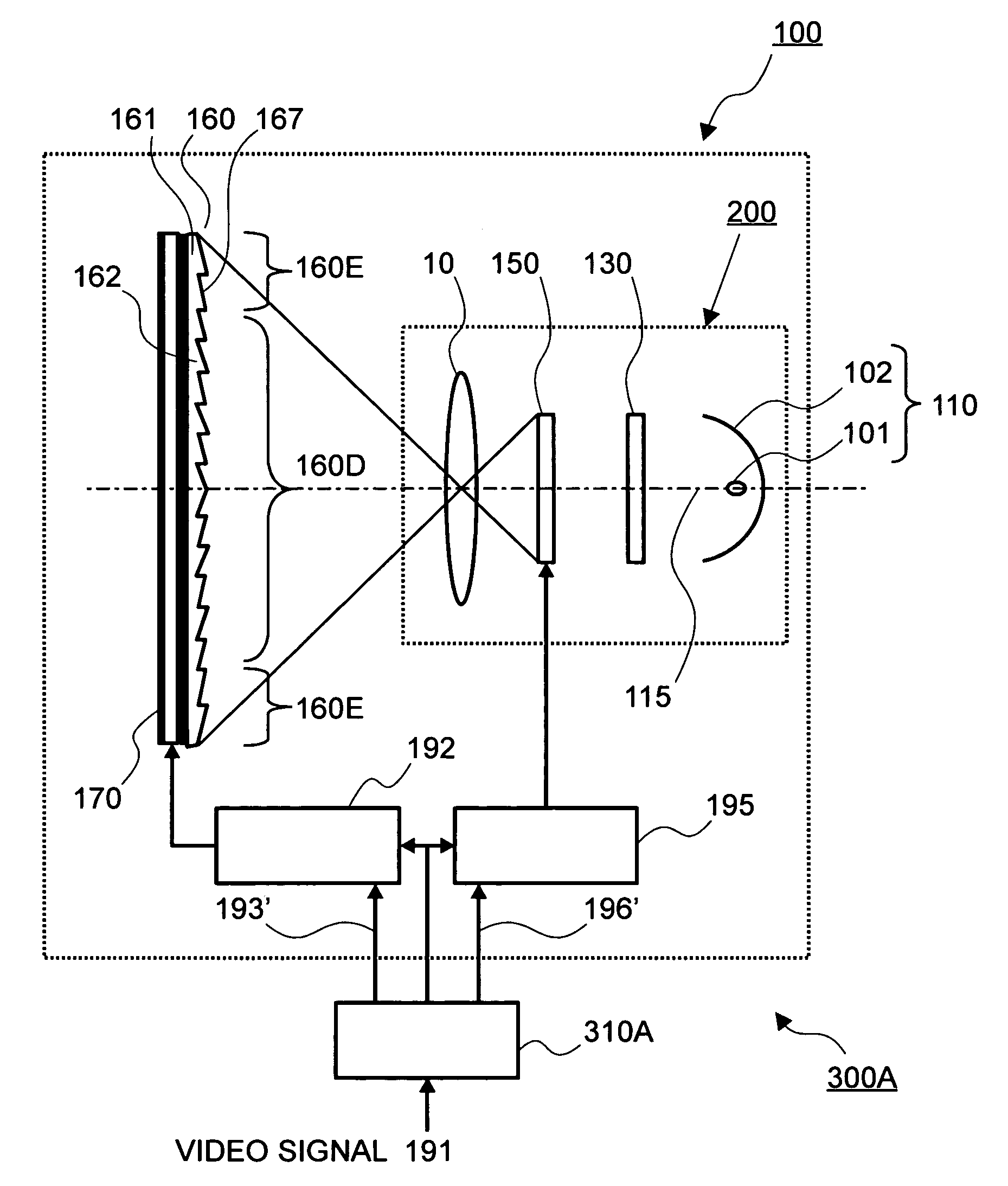
[0145]With the image displaying apparatus shown in FIG. 1, since distribution of an amount of lights (or, distribution of light intensity or distribution of luminance) irradiated from the light source 110 upon the liquid crystal panel is not uniform (or, equalized), there is a possibility of generating unevenness in brightness of the image displayed on the image display liquid crystal panel. Then, explanation will be made on a projection image forming apparatus, according to the embodiment 1, in which an integrator is inserted between the light source and the liquid crystal panel, for informing the light amount distribution of the illumination light from the light source, by referring to FIG. 12.

[0146]FIG. 12 is the structure view of the lighting apparatus, according to the embodiment 1.

[0147]As is shown in FIG. 12, the projection image forming apparatus according to the present embodiment includes a light source 110, a first multi-lens element 121 and a second multi-lens element 12...

embodiment 2

[0159]In the embodiment 1 is used the multi-lens type integrator 120, which is made from the pair of the first multi-lens element 121 and the second multi-lens element 122, as the integrator for uniformizing (or equalizing) the illumination lights. Next, explanation will be made on the lighting apparatus, according to the embodiment 2, applying a rod-type integrator, as a kind of the integrator, by referring to FIG. 14.

[0160]However, as such the rod-type integrator may be applied a light funnel or a rod lens, etc., for example, but herein is applied the light funnel. Also, as the liquid crystal panel, the reflection-type liquid crystal panel is applied, herein. However, the present invention should not be restricted to this, but the rod lens may be applied in the place of the light funnel, and also may be applied a DMD (Digital Micro Mirror Device) element aligning micro mirrors in the 2-D manner, or a transmission-type liquid crystal panel, though it changes the structure of the op...

embodiment 3

[0174]Explanation will be made on an image displaying apparatus, according to an embodiment 3, by referring to FIG. 15.

[0175]The image display apparatus, according to the present embodiment, differs from the embodiment 2 mentioned above, in an aspect that a color wheel is disposed in vicinity of the incident surface 125a of the light funnel 125, as a time-division color separation unit. With using the color wheel, it is possible to achieve time-division display (i.e., sequential color display) of a color image, on the image display light modulation unit for conducting a monochromatic display (i.e., white-black display). Accordingly, in case when conducting the color display, though one (1) pixel is constructed with a set of color pixels (i.e., R-pixel, G-pixel, and B-pixel), however in case of the monochromatic display, since the display is made by one (1) pixel, then it is possible to use a panel having a less number of pixels, as a whole. Then, it is possible to achieve the cost d...


PUM


Abstract

An image displaying apparatus, comprising: a first light modulator unit, which is configured to modulate a light incident thereon, responding to a first video signal, thereby to form a first image; one or a plural number of second light modulator units, which is / are configured to modulate a light from a light source, responding to a second video signal; and an enlarged image forming unit, being disposed on a light incidence side of the first light modulator unit, upon which a light modulated within the second light modulator unit is projected, enlargedly, thereby to form a second image thereon, wherein upon the first light modulator unit is incident the light of the second image formed on the enlarged image forming unit, and the first image is formed through modulation of the light of the second image responding to the first video signal.

Description

BACKGROUND OF THE INVENTION[0001]The present invention relates to an image displaying apparatus for displaying a plural number of two-dimensional (2-D) images on a plural number of display surfaces or screens, which are located at positions differing from each other, in the depth direction of a set seeing from a side of an observer or viewer, and it relates, in particular, to an image displaying apparatus, which can be provided, cheaply, even if enlarging the screen size of the 2-D image.[0002]In recent years, accompanying an announcement of stoppage of the analog terrestrial broadcasting, expected in the year 2011, an image displaying apparatus is widely spreading, of a direct-view type, having a large display, enabling to receive so-called a high vision broadcasting of high-definition (for example, 1,920×1,080 pixels), which was already started, and a digital terrestrial TV (television) broadcasting of high-quality.[0003]In general, as a thin-type display panel within such image d...

Claims


Application Information

Patent Timeline
Patent Type & Authority Patents(United States)
IPC IPC(8): H04N5/74G02B30/25H04N13/395
CPCG02B27/2278H04N13/0495G02F1/133602G02F2001/133601G02F1/1347H04N13/395G02B30/52G02F1/133601
Inventor HIRATA, KOJIYATSU, MASAHIKOIKEDA, HIDEHIRO
Owner MAXELL HLDG LTD
Why Eureka
Try Eureka