Micro plate treating device and micro plate treating method

a micro plate and treating device technology, applied in the field of micro plate treating devices and micro plate treating methods, can solve the problems of unavoidably lowering the functions of the dispensing tip, the device may not be easily handled, and the treatment cannot be promptly and effectively conducted, so as to achieve high treatment efficiency, reduce the area of work, and increase the scale of the device

Active Publication Date: 2013-10-22
UNIVERSAL BIO RESEARCH CO LTD
View PDF27 Cites 11 Cited by
  • Summary
  • Abstract
  • Description
  • Claims
  • Application Information

AI Technical Summary

Benefits of technology

[0040]According to the first aspect of the invention, at least one of the row interval or column interval of the nozzles is a natural number multiple of the row interval or column interval of the corresponding wells, the natural number being two or more; therefore, two or more of the wells can be caused to correspond to one of the nozzles. Accordingly, without setting up any new micro plate, two or more kinds of solutions or the like can be handled in the single micro plate. As a result, a larger number of kinds of solutions or the like can be handled without increasing the area for work.
[0041]Moreover, any one of the nozzles can correspond to two or more of the wells; therefore, a liquid having a volume two or more times larger than the volume handled by any one of the wells can be handled by any one of the nozzles. Furthermore, usable large spaces make their appearance between adjacent ones of the nozzles; therefore, each of the nozzles can be provided with mechanisms for giving various functions, such as a function of applying magnetic force into the nozzle, and a function of detecting the state of the liquid in the nozzle or the like, without enlarging the scale of the device.
[0042]The second or eleventh aspect of the invention produces the advantageous effects of the first aspect of the invention. Besides, the wells which can be handled at a time by any one of the nozzle heads correspond to each of the partial well matrices which belong to the single micro plate and do not overlap with each other, and further the individual partial well matrices are apart from each other only by a distance corresponding to the distance between the wells adjacent to each other in the micro plate; therefore, when a solution or the like that is necessary for a single treatment operation is put into each of the partial well matrices, it is sufficient that the moving distance of the nozzle head which permits the single treatment operation to be completed is short. Thus, the treatment operation can be promptly and effectively conducted.
[0043]According to the third aspect of the invention, for the single micro plate, any one of the nozzle heads is used to make it possible to conduct a series of treatment operations, for many objects to be treated, composed of plural steps continuously to the last; therefore, the treatment efficiency is high for the work area. Additionally, it is sufficient that the moving distance of the nozzle head is short; thus, the working efficiency is high.
[0044]According to the fourth aspect of the invention, each of the well groups includes one unit of each of well elements belonging to each of the partial well matrices, so as to avoid the overlap of two or more units thereof. Therefore, when the nozzles are moved in such a manner that the nozzles can be inserted to all the wells belonging to the well group, a series of treatment operations composed of steps the number of which is at least the natural number (n>1) can be continuously applied to a large number of objects in the single micro plate to the last inside the single micro plate; thus, the device is high in reliability and is easily controlled.
[0045]According to the fifth aspect of the invention, by surrounding a group of the wells in which a treatment operation is applied to one object through any one of the nozzles by the partitions, the treatment operation based on the single nozzle is finished inside the partitions. Thus, the treatment can be conducted without shifting the tip of the nozzle over the partitions. Therefore, cross contamination over the partitions can be certainly prevented. Moreover, the individual nozzles are each moved inside the partitions. Thus, the control of the movement is easy.

Problems solved by technology

As a result, there remains a problem that it is feared that the treatment can neither be promptly nor effectively conducted.
Thus, there remains a problem that is feared that the device may not be easily handled in order to attain the transfer of the nozzle head, or the like.
As a result, there is caused a problem that is feared that functions to be adopted by the dispensing tips are unavoidably lowered.

Method used


Image

  • Micro plate treating device and micro plate treating method
  • Micro plate treating device and micro plate treating method
  • Micro plate treating device and micro plate treating method

Examples


first embodiment

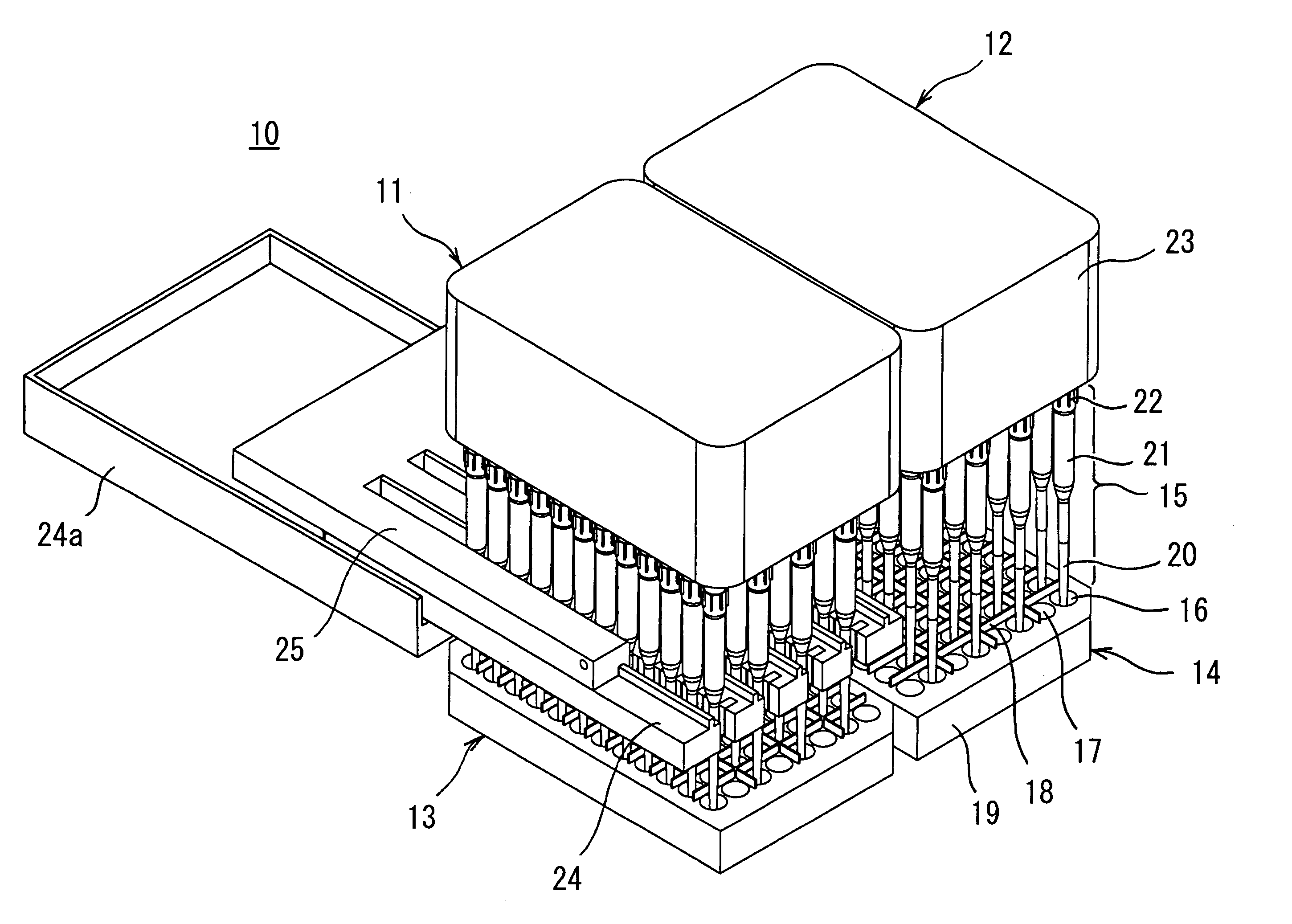
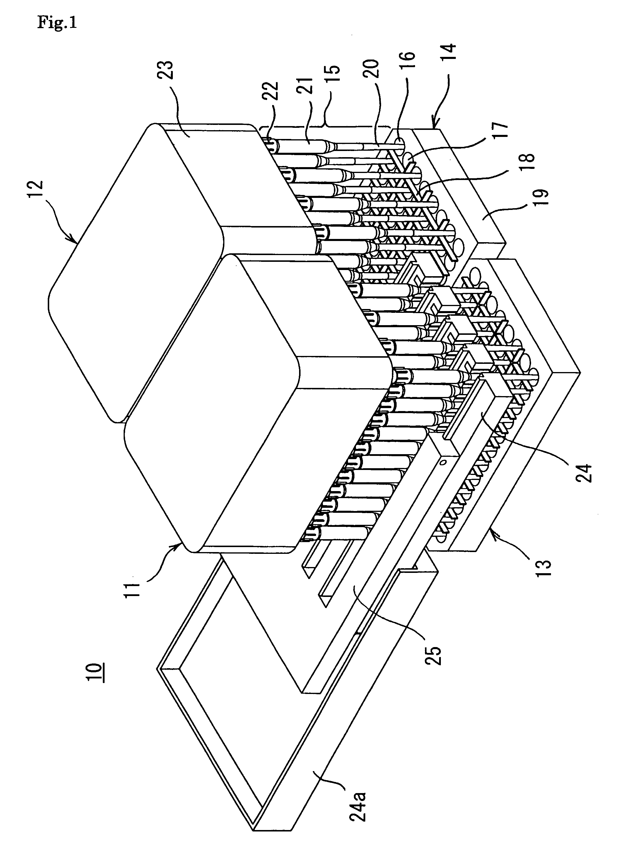
[0062]FIG. 1 is a perspective view of a micro plate treating device 10 according to the invention. The micro plate treating device 10 has two micro plates 13 and 14 wherein wells are arranged in a matrix form, two nozzle heads 11 and 12 each having dispensing tips 15, as nozzle parts, fitted to nozzles which can suck and discharge fluids and are arranged in a matrix form, moving means (not illustrated) for moving the interval between the micro plates 13 and 14 and the nozzle heads 11 and 12 relatively, comb teeth magnets 24 as magnetic force means for applying a magnetic field to the insides of the dispensing tips 15, and comb teeth light-detecting units 25 as light-detecting means for detecting the states of the liquids in the dispensing tips 15. For explanation, one of the comb teeth magnets 24 and one of the comb teeth light-detecting units 25 are illustrated only about the nozzle head 11. Reference numeral 24a represents a tray fitted to be fixed to the nozzle head in order to s...

second embodiment

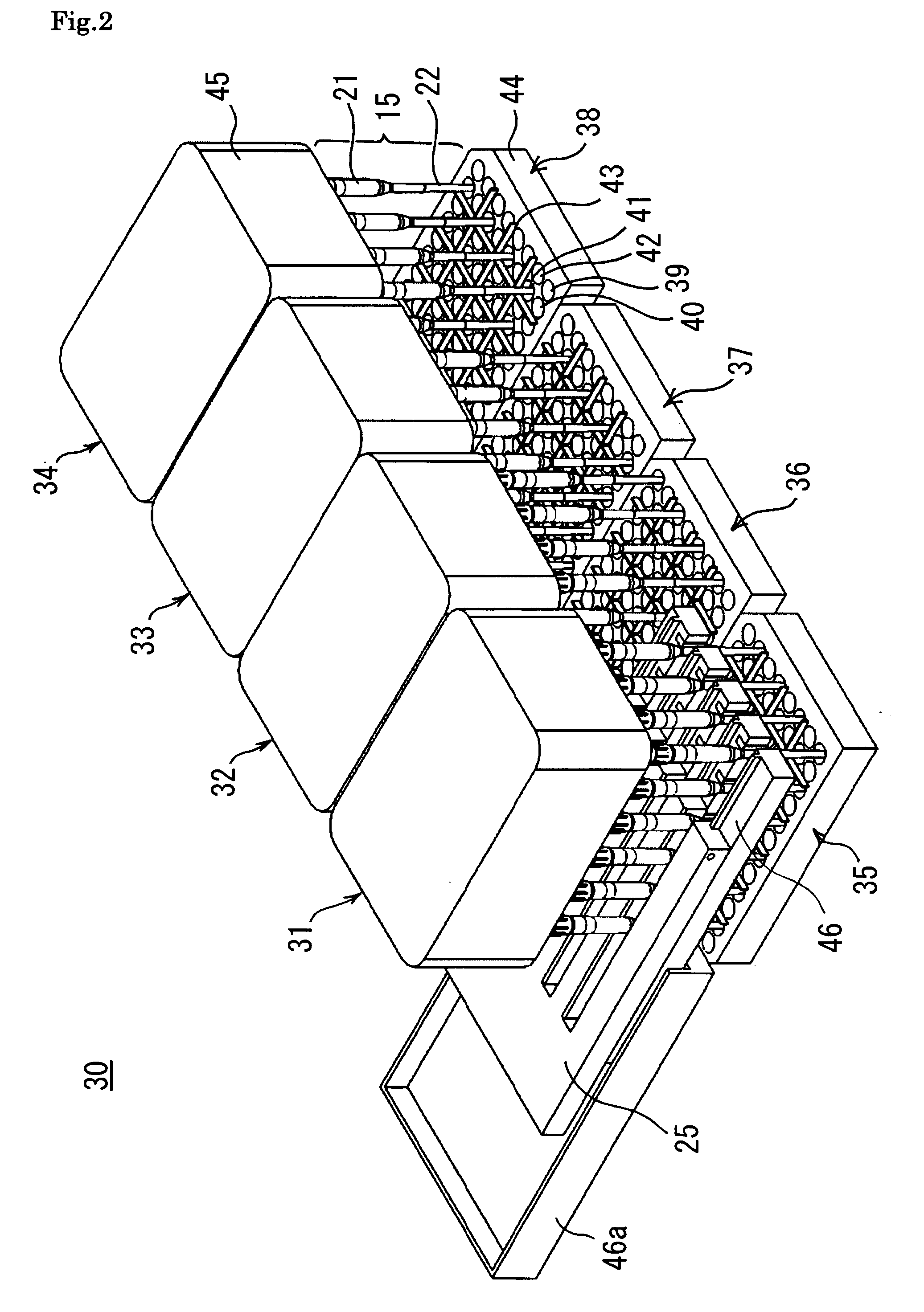
[0086]Next, FIG. 2 is illustrated a perspective view of a micro plate treating device 30 according to the invention. The micro plate treating device 30 has four micro plates 35, 36, 37 and 38 wherein wells are arranged in a matrix form, 4 nozzle heads 31, 32, 33 and 34 each having dispensing tips 15, as nozzle parts, fitted to nozzles which can suck and discharge fluids and are arranged in a matrix form, moving means (not illustrated) for moving the interval between the micro plates 35, 36, 37 and 38 and the nozzle heads 31, 32, 33 and 34 relatively, comb teeth magnets 46 as magnetic force means for applying a magnetic field to the insides of the dispensing tips 15, and comb teeth light-detecting units 25 for detecting the states of the liquids in the dispensing tips 15. For explanation, one of the comb teeth magnets 46 and one of the comb teeth light-detecting units 25 are illustrated only about the nozzle head 31. Reference numeral 46a represents a tray fitted to be fixed to the n...


PUM

PropertyMeasurementUnit
volumeaaaaaaaaaa
distancesaaaaaaaaaa
magnetic fieldaaaaaaaaaa

Abstract

An object is to provide a micro plate treating device and micro plate treating method capable of handling a larger number of kinds of solution or suspensions or a larger volume of solutions or suspensions per work area by use of a normalized micro plate without enlarging the scale of the device.The micro plate treating device comprises a micro plate having wells arranged in a matrix form, one or two or more nozzle heads each having nozzles capable of sucking and discharging a fluid and arranged in a matrix form, and moving means capable of moving relatively an interval between the micro plate and the nozzle heads, wherein tips of all the nozzles are configured to be permitted to be simultaneously inserted into some of the wells in the micro plate, at least one of the row interval or the column interval of the nozzles is set to a natural number multiple of the row interval or the column interval of the corresponding wells, the natural number being two or more, and at least one of the row number or the column number of all the corresponding nozzles is one to the natural number of the row number or the column number of the wells.

Description

CROSS REFERENCE[0001]This application is a United States national phase application of co-pending international patent application number PCT / JP2007 / 056599, filed Mar. 28, 2007,which claims priority to Japanese patent application number 2006-089286, filed Mar. 28, 2006, the disclosures of which are incorporated herein by reference.TECHNICAL FIELD[0002]The present invention relates to a micro plate treating device and a micro plate treating method.BACKGROUND ART[0003]The micro plate is a member wherein pluralities of wells, which can hold liquid, are arranged in a matrix form (row and column form). Known are, for example, 4 rows×6 columns (=24 wells), 6 rows×8 columns (=48 wells), 8 rows×12 columns (=96 wells), 12 rows×16 columns (=192 wells), and 16 rows×24 columns (=384 wells). The intervals between the individual wells in these micro plates tend to be normalized. In, for example, a micro plate having 96 wells, the row interval thereof, which is the distance in the column direction...

Claims


Application Information

Patent Timeline
Patent Type & Authority Patents(United States)
IPC IPC(8): B01L3/02B03C1/30C02F1/48G01N33/553
CPCB01L3/5085G01N35/1074G01N1/28B01L9/54B01L2200/141Y10T436/2575B01L2300/0829
Inventor TAJIMA, HIDEJI
Owner UNIVERSAL BIO RESEARCH CO LTD
Why Eureka
Try Eureka