Micro Plate Treating Device and Micro Plate Treating Method
a micro plate and treating device technology, applied in the field of micro plate treating devices and micro plate treating methods, can solve the problems of unavoidably lowering the functions of the dispensing tip, the device may not be easily handled, and the treatment cannot be promptly and effectively conducted, so as to achieve high treatment efficiency, reduce the area of work, and increase the scale of the device
- Summary
- Abstract
- Description
- Claims
- Application Information
AI Technical Summary
Benefits of technology
Problems solved by technology
Method used
Image
Examples
first embodiment
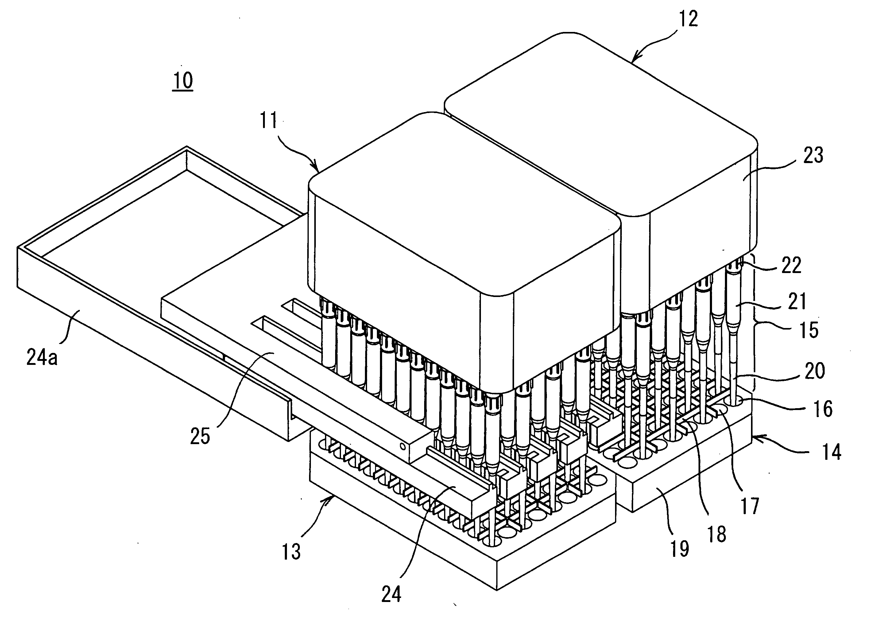
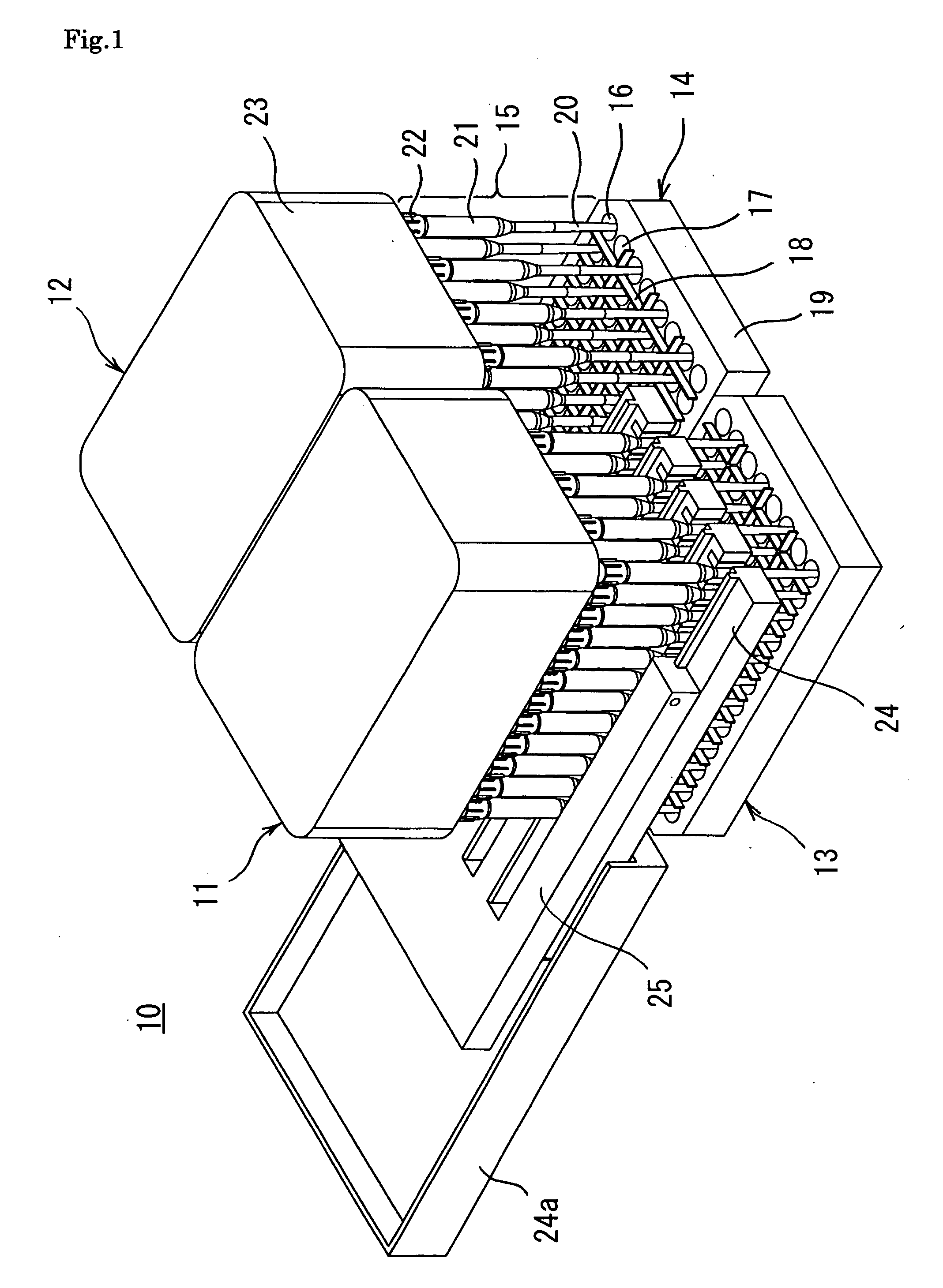
[0061]FIG. 1 is a perspective view of a micro plate treating device 10 according to the invention. The micro plate treating device 10 has two micro plates 13 and 14 wherein wells are arranged in a matrix form, two nozzle heads 11 and 12 each having dispensing tips 15, as nozzle parts, fitted to nozzles which can suck and discharge fluids and are arranged in a matrix form, moving means (not illustrated) for moving the interval between the micro plates 13 and 14 and the nozzle heads 11 and 12 relatively, comb teeth magnets 24 as magnetic force means for applying a magnetic field to the insides of the dispensing tips 15, and comb teeth light-detecting units 25 as light-detecting means for detecting the states of the liquids in the dispensing tips 15. For explanation, one of the comb teeth magnets 24 and one of the comb teeth light-detecting units 25 are illustrated only about the nozzle head 11. Reference numeral 24a represents a tray fitted to be fixed to the nozzle head in order to s...
second embodiment
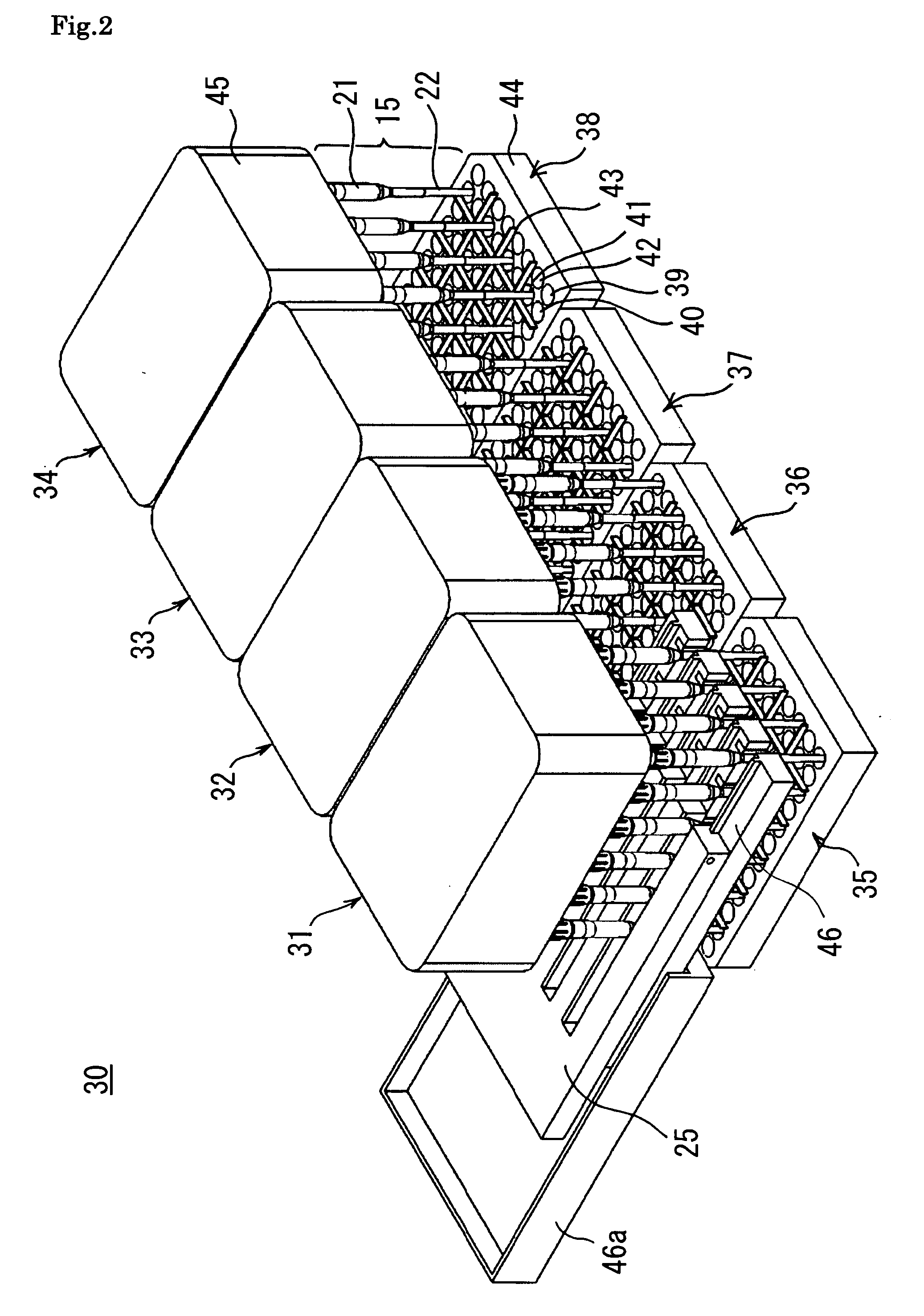
[0085]Next, FIG. 2 is illustrated a perspective view of a micro plate treating device 30 according to the invention. The micro plate treating device 30 has four micro plates 35, 36, 37 and 38 wherein wells are arranged in a matrix form, 4 nozzle heads 31, 32, 33 and 34 each having dispensing tips 15, as nozzle parts, fitted to nozzles which can suck and discharge fluids and are arranged in a matrix form, moving means (not illustrated) for moving the interval between the micro plates 35, 36, 37 and 38 and the nozzle heads 31, 32, 33 and 34 relatively, comb teeth magnets 46 as magnetic force means for applying a magnetic field to the insides of the dispensing tips 15, and comb teeth light-detecting units 25 for detecting the states of the liquids in the dispensing tips 15. For explanation, one of the comb teeth magnets 46 and one of the comb teeth light-detecting units 25 are illustrated only about the nozzle head 31. Reference numeral 46a represents a tray fitted to be fixed to the n...
PUM
| Property | Measurement | Unit |
|---|---|---|
| volume | aaaaa | aaaaa |
| distances | aaaaa | aaaaa |
| magnetic field | aaaaa | aaaaa |
Abstract
Description
Claims
Application Information
 - R&D
- Intellectual Property
- Life Sciences
- Materials
- Tech Scout
- Unparalleled Data Quality
- Higher Quality Content
- 60% Fewer Hallucinations
Browse by: Latest US Patents, China's latest patents, Technical Efficacy Thesaurus, Application Domain, Technology Topic, Popular Technical Reports.
© 2025 PatSnap. All rights reserved.Legal|Privacy policy|Modern Slavery Act Transparency Statement|Sitemap|About US| Contact US: help@patsnap.com


