Image forming optical element, image forming optical array, and image reading device

a technology of image forming optical array and image forming optical element, which is applied in the direction of instruments, gymnastics, weights, etc., can solve the problems of reducing the degree of freedom in disposition of optical sensors, difficult to avoid complication of image forming optical units, suppressing the decrease of light efficiency, etc., and achieves simple configuration and high precision positioning.

Active Publication Date: 2014-02-11
SEIKO EPSON CORP
View PDF2 Cites 0 Cited by
  • Summary
  • Abstract
  • Description
  • Claims
  • Application Information

AI Technical Summary

Benefits of technology

[0016]With such a configuration, the reflection face is a curved face and has power, and thus the image forming optical element is miniaturized and performance of forming an image is improved.Application Example 5
[0057]Accordingly, in the image forming optical element, the incident unit, the output unit, and the bent unit including the reflection face are integrally formed. Therefore, when the image forming optical element is provided in the image reading device, it is not necessary to match the relative positions of the incident unit, the output unit, and the bent unit, it is not necessary to perform positioning of the image forming optical element with high precision, and thus it is possible to simply configure the image forming optical element, and it is possible to easily and efficiently form the erection image of the object based on an image forming optical system without decreasing efficiency of using light since there is no air in an optical path from the incident unit to the output unit.

Problems solved by technology

This is one of main factors decreasing the degree of freedom in disposition of the optical sensor.
However, in the roof prism lens array, an object side lens face and an image forming side lens face are perpendicularly disposed, a structure in which a ridge is disposed to be 45° with respect to a plane including the optical axes of two lenses is employed, and thus it is difficult to avoid complication of the image forming optical unit.
With such a configuration, since there is no air in the optical path from the incident unit and the output unit, and thus it is possible to suppress a decrease of efficiency of using light.

Method used


Image

  • Image forming optical element, image forming optical array, and image reading device
  • Image forming optical element, image forming optical array, and image reading device
  • Image forming optical element, image forming optical array, and image reading device

Examples


first embodiment

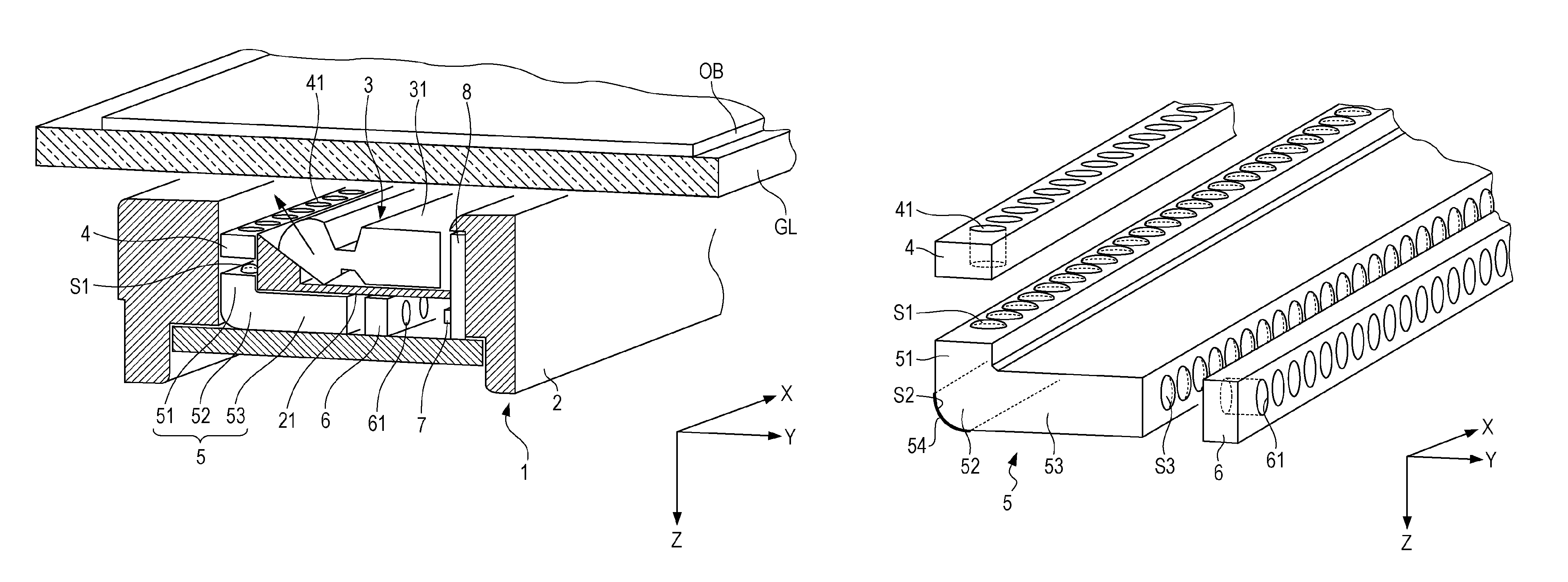
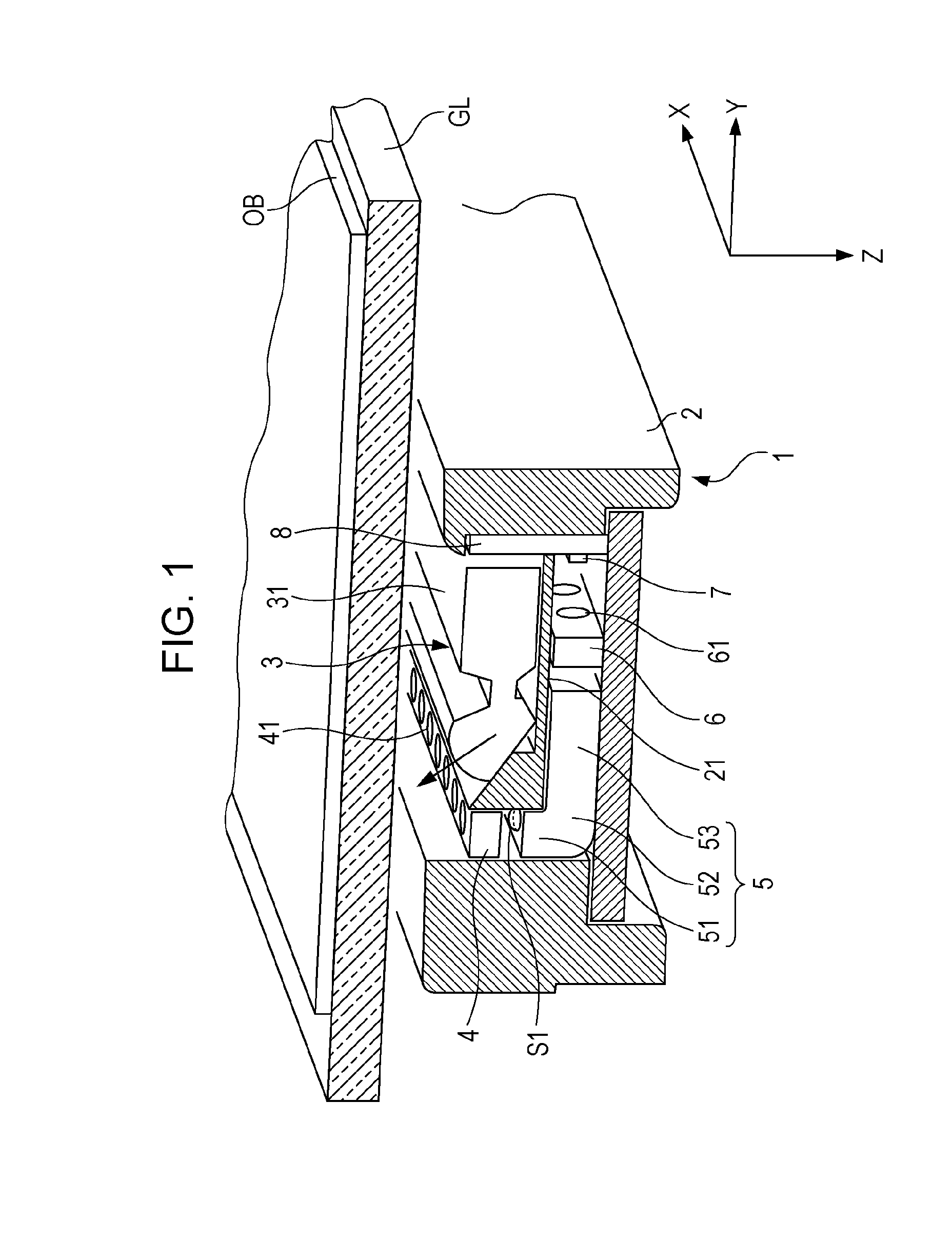
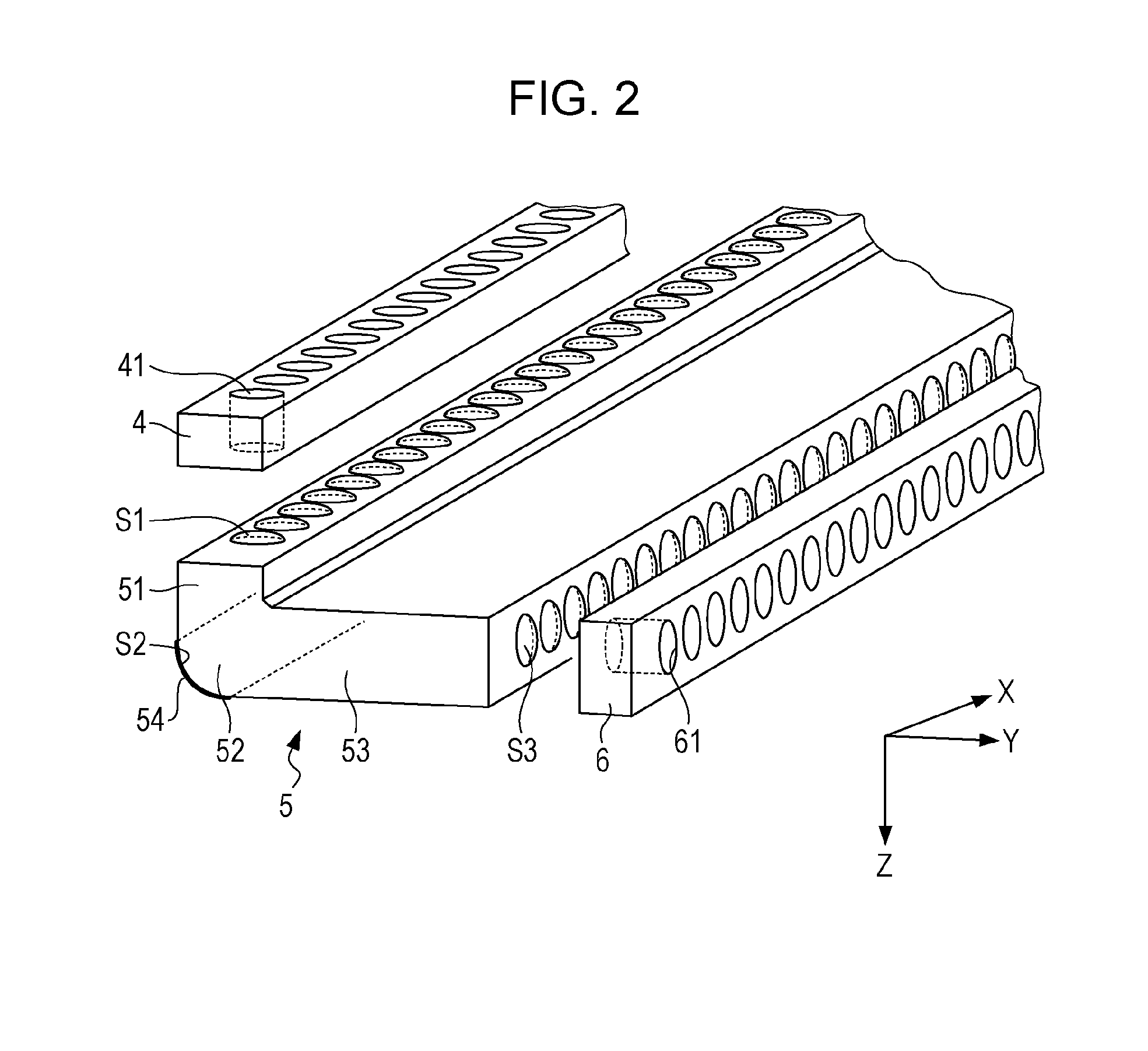
[0074]FIG. 1 is a partial cross-sectional perspective view illustrating a CIS module of an image reading device according to the invention. FIG. 2 is a perspective view illustrating an incident side aperture member, a lens array, and an output side aperture member in the CIS module shown in FIG. 1. The CIS module 1 is a device that reads an original document OB placed on an original document glass GL to read an image printed on the original document OB as a reading target, and is disposed just under the original document glass GL. The CIS module 1 has a rectangular frame 2 extending longer than a reading range of the original document OB in an X direction, and is provided with a light source unit 3, an incident side aperture member 4, a lens array 5, an output side aperture member 6, a sensor 7, and a printed circuit board 8 in the frame 2.

[0075]A separator 21 is disposed in the frame 2, and thus an internal space of the frame 2 is separated into an upper space for disposing the lig...

second embodiment

[0090]FIG. 3 is a partial cross-sectional perspective view illustrating the CIS module of the image reading device according to the invention. FIG. 4 is a perspective diagram illustrating the incident side aperture member, the lens array 5, and the output side aperture member in the CIS module shown in FIG. 3. The CIS module 1 is a device that reads an original document OB placed on an original document glass GL to read an image printed on the original document OB as a reading target, and is disposed just under the original document glass GL. The CIS module 1 has a rectangular frame 2 extending longer than a reading range of the original document OB in an X direction, and is provided with a light source unit 3, an incident side aperture member 4, a lens array 5, an output side aperture member 6, a sensor 7, and printed circuit boards 8A and 8B in the frame 2.

[0091]A separator 21 is disposed in the frame 2, and thus an internal space of the frame 2 is separated into an upper space fo...

third embodiment

[0120]First, FIG. 13 will be described. In the third embodiment, the connection unit 52 is formed of an incident unit 51 growing in the Z direction, left and right portions 55 curved from the lower end of the incident unit 51 and extending to the right side, and an output unit 53 curved from the right end of the left and right portions 55 and extending downward. That is, the connection unit 52 has a shape perpendicularly curved by a first curve portion CV1 from the incident unit 51 to the left and right portions 55 and perpendicularly curved by a second curve portion CV2 from the left and right portions 55 to the output unit 53.

[0121]On the upper face of the incident unit 51, a plurality of incident side lens faces S1 corresponding to, one-to-one, a plurality of through-holes 41 of the incident side aperture member 4 are formed in a line at a predetermined pitch in the X direction. On the lower face of the output unit 53 of the connection unit 52, a plurality of output side lens fac...


PUM


Abstract

An image forming optical element is provided, in which an incident unit having a first lens face to which a light beam output from an original document (object) is input, an output unit having a second lens face outputting the light beam, and a bent unit connecting the incident unit and the output unit at an angle are integrally formed into a transparent medium. The bent unit has a reflection face reflecting the incident light beam input to the first lens face and guiding the light beam to the second lens face. The incident light beam is collected at any of the incident unit, the bent unit, and the output unit to form an intermediate image of the object, and the intermediate image is formed on the output side of the second lens face to form an erection image of the object.

Description

CROSS REFERENCES TO RELATED APPLICATIONS[0001]The entire disclosure of Japanese Patent Application Nos. 2011-010591, filed Jan. 21, 2011, 2011-010592, filed Jan. 21, 2011, 2011-010593, filed Jan. 21, 2011, 2011-010746, filed Jan. 21, 2011 and 2011-010747, filed Jan. 21, 2011 are expressly incorporated by reference herein.BACKGROUND[0002]1. Technical Field[0003]The present invention relates to an image forming optical element that forms an erected image of an object, an image forming optical array, and an image reading device that reads an image of an object using the image forming optical element.[0004]2. Related Art[0005]In an image scanner, a facsimile, a copier, a financial terminal device, a contact image sensor module (hereinafter, referred to as “CIS module”) is used as an image reading device. The CIS module has a light source unit that irradiates a reading target with light, an image forming optical unit that forms a erection equal-magnification image of the reading target, ...

Claims


Application Information

Patent Timeline
Patent Type & Authority Patents(United States)
IPC IPC(8): H04N1/04
CPCH04N2201/02479H04N2201/02458H04N2201/02456H04N1/0306H04N1/0318H04N1/0315H04N1/0312H04N2201/02462G02B17/086A61H39/04A63B21/075A63B23/0233A63B23/12A63B2023/006A63B2208/12
Inventor TAKEDA, TAKASHI
Owner SEIKO EPSON CORP
Why Eureka
Try Eureka