Accommodating intraocular lens

a monofocal, intraocular lens technology, applied in the field of surgical implanted eye prosthesis, can solve the problems of hazy capsules, unable to focus eyes of patients with monofocal intraocular lens, and unable to achieve the effect of focusing eyes and bright colors

Active Publication Date: 2014-07-08
UNIV OF SOUTHERN CALIFORNIA +1
View PDF26 Cites 112 Cited by
  • Summary
  • Abstract
  • Description
  • Claims
  • Application Information

AI Technical Summary

Benefits of technology

[0019]Systems, devices, and methods of the present application are related to an intraocular lens having one or more valve areas consisting of an elastomeric patch. The elastomeric patch is sized such that it self-seals after a needle puncture, such that the optically transparent fluid within the intraocular lens can be injected or withdrawn in order to adjust a lens after implantation. A slit can be manufactured into the patch that is sized for self-closing and allows standard gauge surgical needles to pass through. The patch can include a stepped area for additional closing power. The patch can be brightly colored so that it is more easily found by a surgeon. In another design, a wagon-wheel shaped valve with a plurality of wedge-shaped openings can be encapsulated in the walls of the lens. The center of the wagon wheel or each of the wedge-shaped openings can be pierced by a needle.
[0021]Adhesive can be used to not only form a bond between an intraocular lens and the lens capsule but also placed to prevent cells from migrating to the optical center region of the lens.
[0032]Some embodiments are related to a method of coupling an intraocular lens apparatus and a lens capsule. The method includes applying a circular annulus of adhesive, and implanting a lens apparatus such that the circular annulus of adhesive adheres the lens apparatus to a lens capsule, the circular annulus of adhesive forming a barrier to prevent migration of cells.

Problems solved by technology

This makes the capsule hazy and creates visual disturbances.
Therefore, patients with a monofocal intraocular lens can no longer focus their eyes.
This makes it difficult to focus on near objects.
However, because of the unique optical design, patients may have a loss of sharpness of vision even when glasses are used.
Patients can also experience visual disturbances such as halos or glare.

Method used


Image

  • Accommodating intraocular lens
  • Accommodating intraocular lens
  • Accommodating intraocular lens

Examples


Embodiment Construction

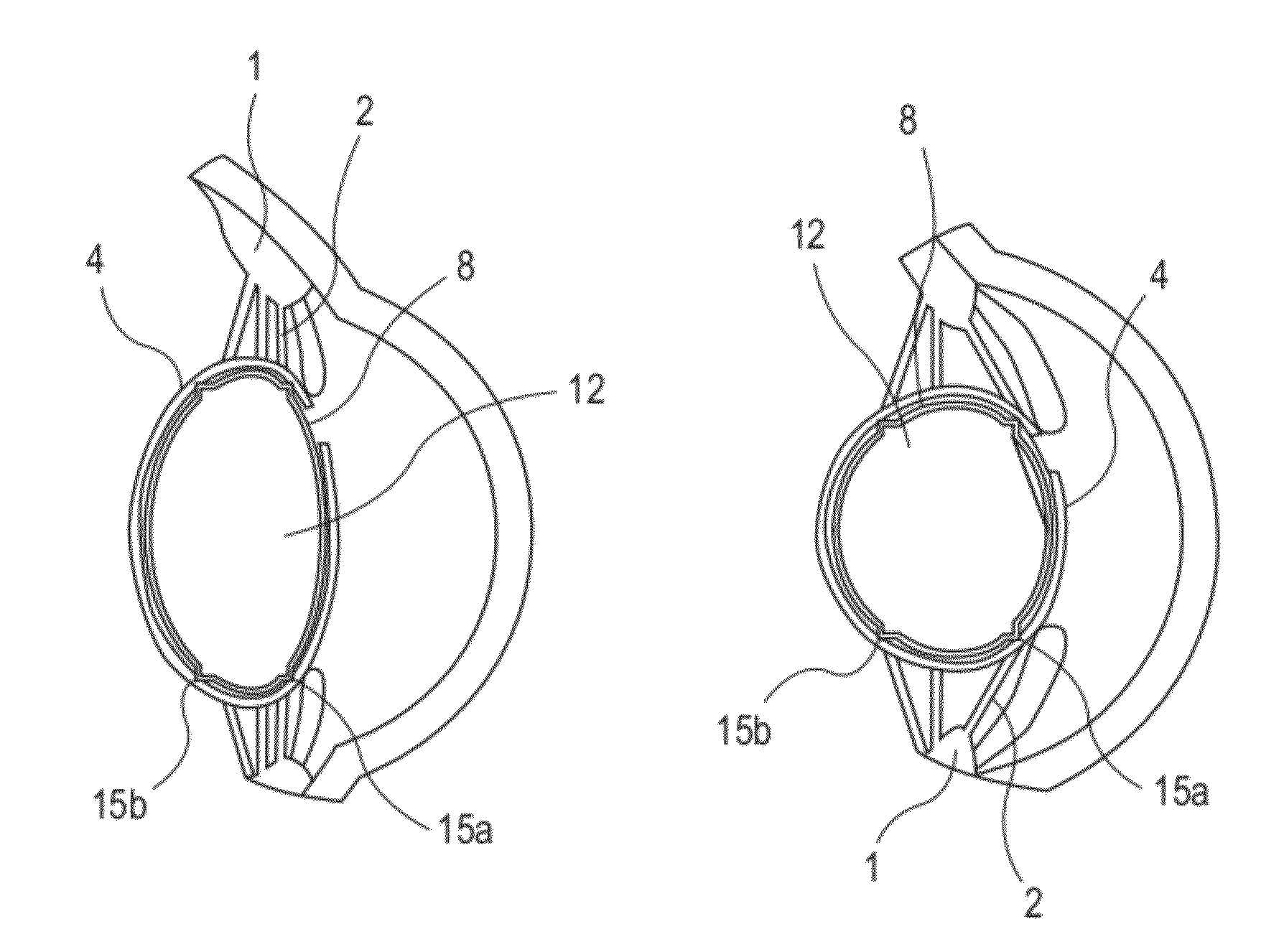
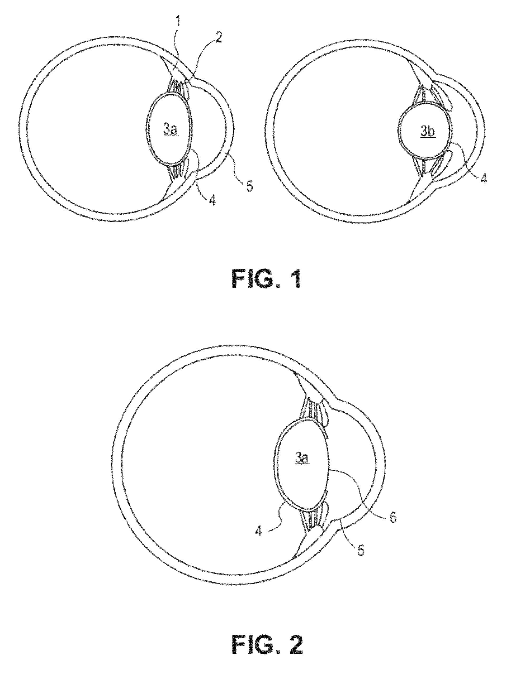
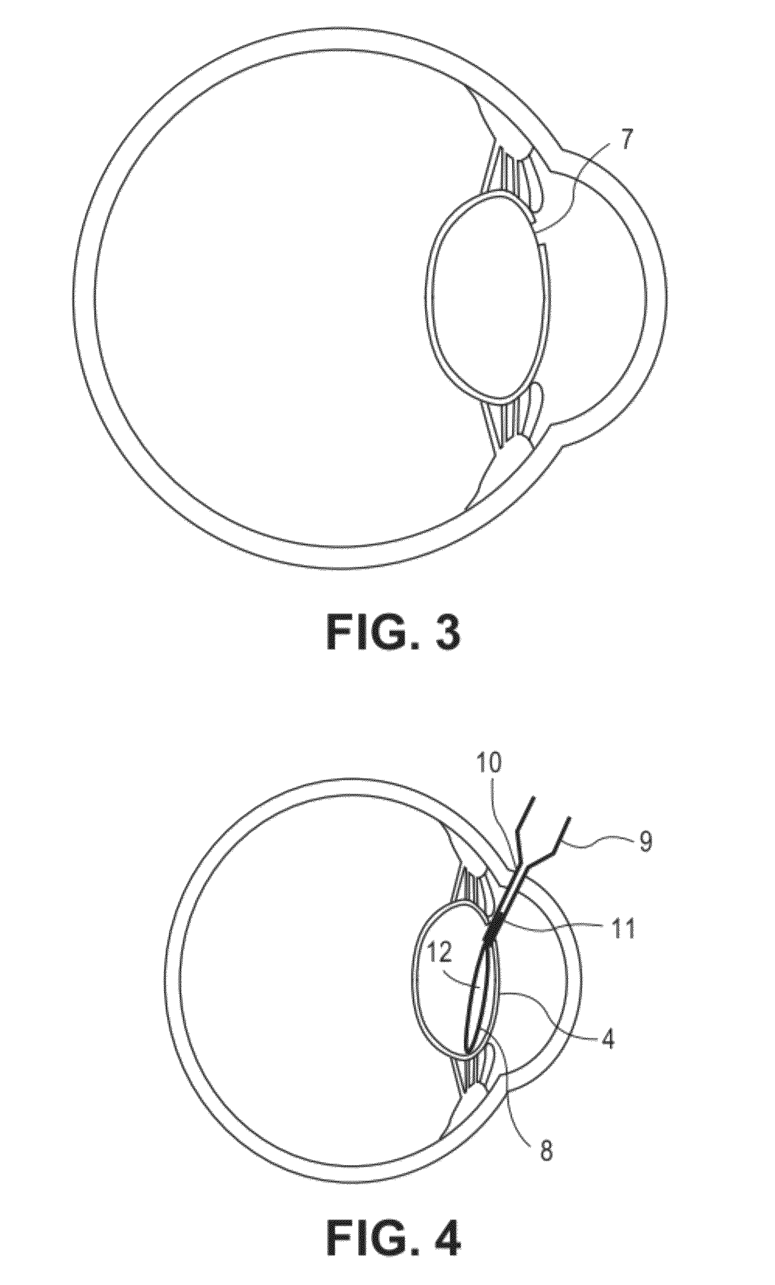
[0062]An injectable accommodating intraocular lens system is disclosed as well as devices and systems relating thereto. In various embodiments, the lens is constructed to form a flexible, thin, biocompatible bag. During surgery, the bag is filled with an optically clear medium, such as silicone fluid. During insertion into the lens capsule of the eye, the intraocular lens has little or no medium in it in order to reduce its overall dimensions, allowing insertion through a small surgical incision. After insertion, the intraocular lens is inflated with the clear medium to a target dioptric power. Once inserted, the accommodating intraocular lens deforms in response to the natural focusing mechanism of the existing ciliary muscle to change focus in a manner similar to a human lens.

[0063]Because of its ability to fit through small incisions, the injectable accommodating intraocular lens can be used with minimally invasive surgical techniques, making recovery time for a patient more rapi...


PUM

PropertyMeasurementUnit
thicknessaaaaaaaaaa
thicknessaaaaaaaaaa
thicknessaaaaaaaaaa

Abstract

Systems, devices, and methods are presented for a prosthetic injectable intraocular lens. One or more silicone elastomeric patches located outside the optical path on the anterior side but away from the equator can be accessed by surgical needles in order to fill or adjust optically clear fluid within the lens. The fluid can be adjusted in order to set a base dioptric power of the lens and otherwise adjust a lens after its initial insertion. The elastomeric patches are sized so that they self-seal after a needle is withdrawn. A straight or stepped slit in the patch can allow a blunt needle to more easily access the interior of the lens.

Description

STATEMENT AS TO RIGHTS TO INVENTIONS MADE UNDER FEDERALLY SPONSORED RESEARCH OR DEVELOPMENT[0001]This invention was made with government support under EEC0310723 awarded by the National Science Foundation. The government has certain rights in the invention.CROSS-REFERENCES TO RELATED APPLICATIONS[0002]This application claims the benefit of U.S. Provisional Application No. 61 / 526,147, filed Aug. 22, 2011, and U.S. Provisional Application No. 61 / 488,964, filed May 23, 2011, which are hereby incorporated by reference in their entireties for all purposes.BACKGROUND[0003]1. Field of the Art[0004]Embodiments of the present invention generally relate to surgically implanted eye prostheses, in particular, to microfabricated, fluid-filled intraocular lens devices.[0005]2. Description of the Related ArtSurgical Procedure[0006]An intraocular lens (IOL) can be used to replace a natural crystalline lens in human patients. Surgically replacing the crystalline lens includes making a main incision ...

Claims


Application Information

Patent Timeline
Patent Type & Authority Patents(United States)
IPC IPC(8): A61F2/16
CPCA61F2/1635A61F2/1613A61F9/0017A61F2250/0003A61L27/48A61L2430/16C08G2261/3424C08L65/04A61F9/007
Inventor DEBOER, CHARLESTAI, YU-CHONGHUMAYUN, MARK
Owner UNIV OF SOUTHERN CALIFORNIA
Why Eureka
Try Eureka