Check patentability & draft patents in minutes with Patsnap Eureka AI!

Rotation angle detecting unit

a detection unit and rotation angle technology, applied in the direction of mechanical measuring arrangements, instruments, digital computer details, etc., can solve the problems of increasing examination costs, material costs and processing costs for the covering of the ic package with the elastic body, and deteriorating temperature characteristics of the output of the magnetism detecting elemen

Active Publication Date: 2014-07-15
DENSO CORP
View PDF15 Cites 2 Cited by
  • Summary
  • Abstract
  • Description
  • Claims
  • Application Information

AI Technical Summary

Benefits of technology

This configuration reduces examination costs, stabilizes the position of the magnetism detecting element, improves detection accuracy, and prevents damage from thermal stress, while maintaining the integrity of the magnetism detecting element.

Problems solved by technology

However, when thermal stress is applied to the IC package due to a difference in linear expansion between the IC package and the resin of the covering member, there is a possibility that temperature characteristics of output of the magnetism detecting element may deteriorate.
As a result of this, costs for the examination will increase.
Thus, in addition to the above-described problems, there is a problem that material costs and processing costs for the covering of the IC package with the elastic body will increase.

Method used


Image

  • Rotation angle detecting unit
  • Rotation angle detecting unit
  • Rotation angle detecting unit

Examples


Embodiment Construction

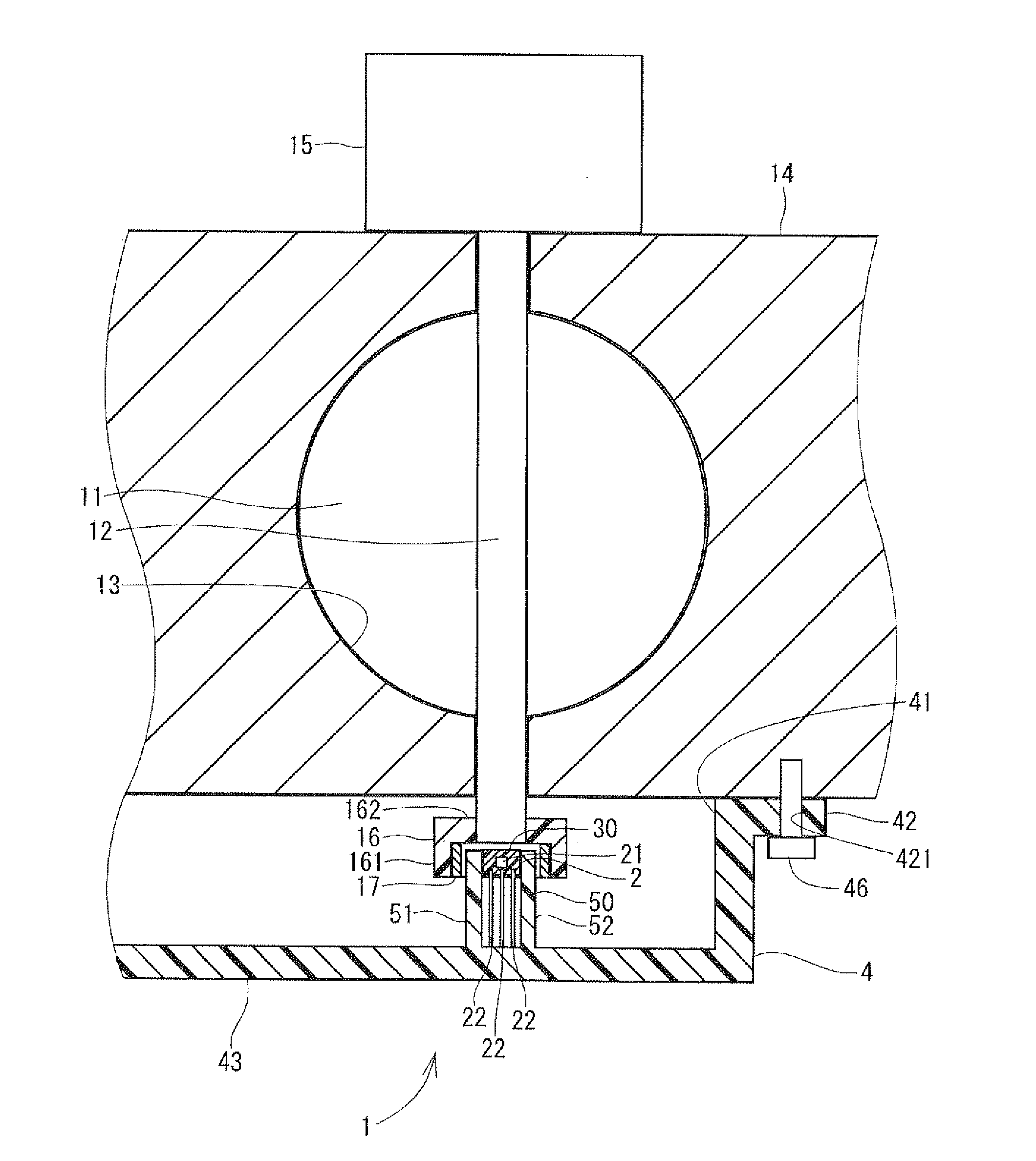
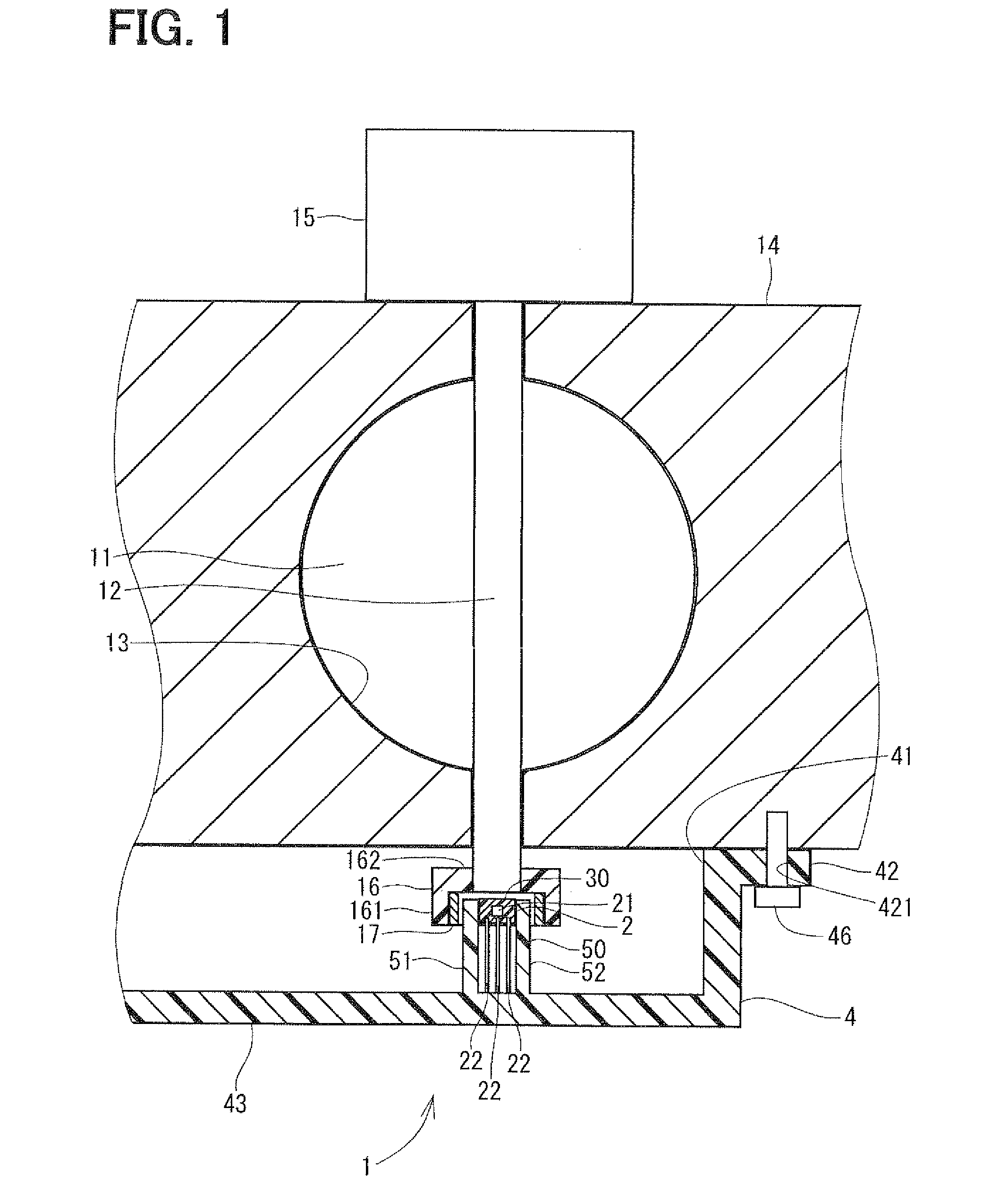
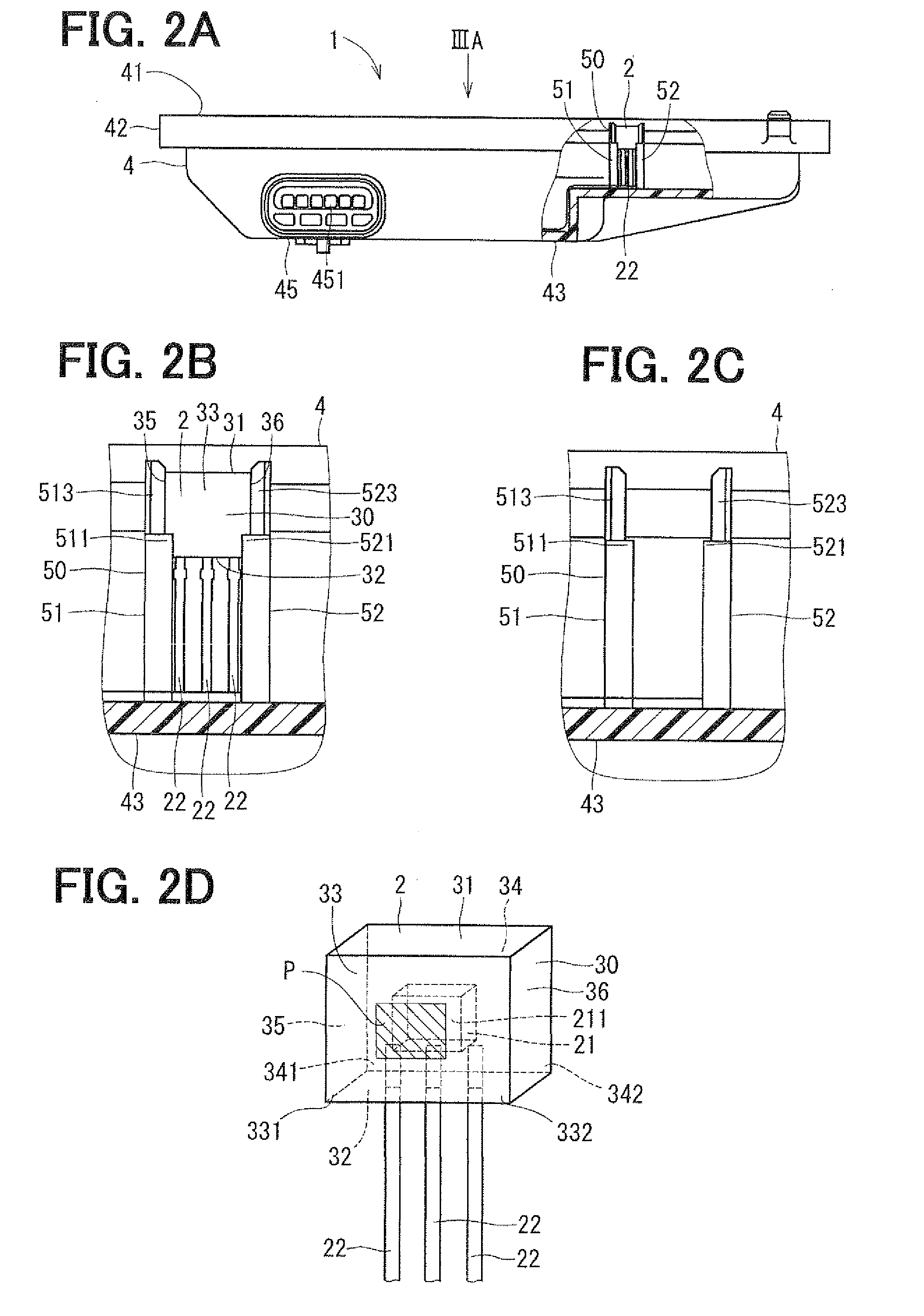
[0018]An embodiment of the invention will be described below in reference to the accompanying drawings. A rotation angle detecting unit according to the embodiment of the invention will be described in FIGS. 1 to 3B.

[0019]The rotation angle detecting unit 1 of the present embodiment is used for calculating a degree of opening of a throttle valve 11 disposed in a vehicle. The rotation angle detecting unit 1 detects a rotation angle of a valve stem 12 of the throttle valve 11 as a detection object.

[0020]First, the throttle valve 11 will be described. As illustrated in FIG. 1, the throttle valve 11 is formed in the shape of a generally circular disk, and disposed in an intake passage 13. The valve stem 12 is formed integrally with the throttle valve 11 to pass through the center of the throttle valve 11 in a direction of a plate surface of the valve 11. Portions of the valve stem 12 on both side of the throttle valve 11 are shaft-borne by a throttle body 14 that define the intake passa...


PUM


Abstract

A rotation angle detecting unit includes an IC package having a magnetism detecting element, a sealing body, and leads; and a covering member having a fixing part and a supporting part, which are integrally formed from resin. The element outputs a signal according to change of a magnetic field generated upon rotation of a magnetism generating device attached to a detection object. The sealing body covers the element. The leads are connected to the element, and project from the sealing body. The fixing part is fixed to a supporting body so that the covering member is attached to the supporting body. The supporting part supports the package such that the element can output the signal. The package is press-fitted into the supporting part after its formation, so that the package is supported by the supporting part with a predetermined pressure applied to part of an outer wall of the sealing body.

Description

CROSS REFERENCE TO RELATED APPLICATION[0001]This application is based on and incorporates herein by reference Japanese Patent Application No. 2010-206654 filed on Sep. 15, 2010.BACKGROUND OF THE INVENTION[0002]1. Field of the Invention[0003]The present invention relates to a rotation angle detecting unit that detects a rotation angle of a detection object.[0004]2. Description of Related Art[0005]A rotation angle detecting unit obtained as a result of molding an integrated circuit (IC) package, which includes a magnetism detecting element, in a covering member made of resin, is conventionally known (see, e.g., JP-A-2004-004114 corresponding to U.S. Pat. No. 6,407,543B1). The covering member is attached to a supporting body that rotatably supports a detection object. In this rotation angle detecting unit, the covering member and the IC package are integrally formed (resin-molded), so that a position of the magnetism detecting element is stabilized, and accuracy in detection of a rotat...

Claims


Application Information

Patent Timeline
Patent Type & Authority Patents(United States)
IPC IPC(8): G01B7/30
CPCG01D11/245G01D5/145
Inventor HIRAMOTO, SATORUKONO, YOSHIYUKIMIZUTANI, AKITOSHIMATSUMOTO, KOICHIRO
Owner DENSO CORP
Features
  • R&D
  • Intellectual Property
  • Life Sciences
  • Materials
  • Tech Scout
  • Unparalleled Data Quality
  • Higher Quality Content
  • 60% Fewer Hallucinations
Learn More