

Fiber optic adapter module and tray
a fiber optic adapter and fiber optic technology, applied in the field of fiber optic adapter modules and fiber optic equipment racks, can solve the problems of difficult hand access by technicians to optical components and connectors, difficult routing and organizing of jumper connections, and complex fiber management, etc., to achieve convenient access, convenient routing, and high density
- Summary
- Abstract
- Description
- Claims
- Application Information
AI Technical Summary
Benefits of technology
Problems solved by technology
Method used
Image

Examples
Embodiment Construction
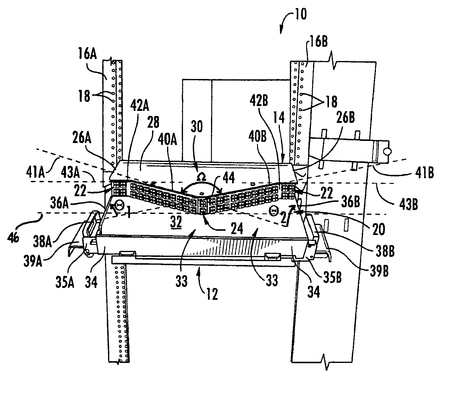
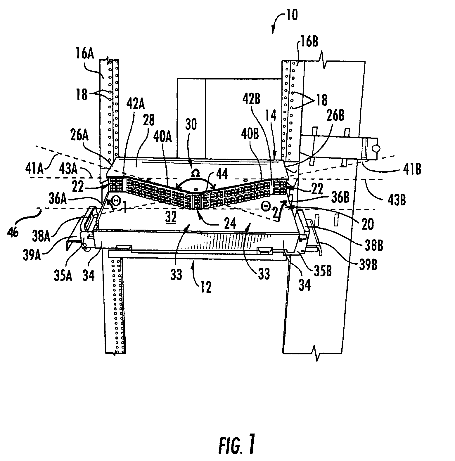
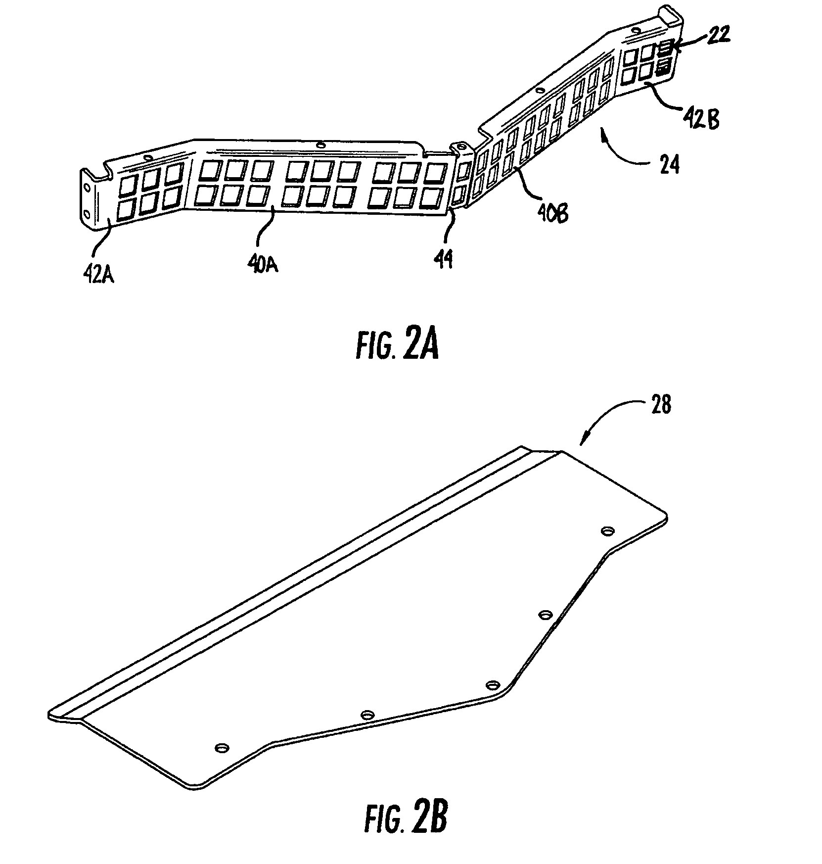
[0008]Embodiments disclosed in the detailed description include a fiber optic adapter module for supporting high density fiber optic connections. The fiber optic adapter module includes an adapter module panel supporting a plurality of fiber optic adapters that provides enhanced convenient access and neat routing and organizing of high density fiber optic connections. In one embodiment, the adapter module panel contains at least two forward facing panel surfaces angled to one another. Angled panel surfaces provide more surface area on the adapter module panel for supporting high density fiber optic adapters and increasing hand access space to the fiber optic adapters. A third and / or fourth flared panel surface may also be included on or proximate to ends of the adapter module panel and intersecting with the angled panel modules. Providing flared panel surfaces allows room for additional fiber optic adapters to be supported on or proximate to the ends of the adapter module panel for ...
PUM
 Abstract
Description
Claims
Application Information