Linear motion module

a technology of linear motion and motion module, which is applied in the direction of linear bearings, shafts and bearings, bearings, etc., can solve the problems of instability of circulation motion of balls, passage diameter, and conventional art, and achieve the effects of enhancing the motion stability of balls, uniform diameter, and reducing noise during the motion of linear motion modules

Active Publication Date: 2015-04-14
TBI MOTION TECH CO LTD
View PDF4 Cites 6 Cited by
  • Summary
  • Abstract
  • Description
  • Claims
  • Application Information

AI Technical Summary

Benefits of technology

[0020]As mentioned above, according to the linear motion module of the invention, the circulation element can replace the circulation channel to act a part of the outer circulation passage, so the machining defect of the circulation channel is not a problem anymore and the circulation passage can have uniform diameter. Besides, because the manufacturing method and connection relationship of the circulation element are favorable to form the passage wall without sectional difference, the noise during the motion of the linear motion module can be reduced and the motion stability of the balls can be enhanced. Furthermore, when the positioning structure and / or the self-lubricating element are applied in the invention, the positioning and / or lubricating functions can be provided. Moreover, because the opposite two circulation elements and / or the end caps with the ball holders can be made by an integrally forming manner, the number of the components, the cost and the machining steps can be all reduced and therefore the tolerance caused by the multiple assemblies can be avoided.
[0021]In comparison with the prior art, due to the structural design, the linear motion module of the invention can overcome the disadvantages such as the taper of the tube diameter or the roughness of the passage surface, which are unfavorable to the motion of the balls, and therefore the noise during the motion can be reduced and the motion stability can be increased. Besides, by the self-lubricating element providing the lubricant, the interference between the balls or between the balls and the circulation passage can be reduced. When the integrally forming method is applied to the linear motion module of the invention, the number of the components can be reduced and the components within the sliding block can be combined as a single piece. Therefore, the circulation passage can tightly fit the sliding block body to obtain stronger supporting force, and thus the passage vibration during the motion of the balls can be avoided.

Problems solved by technology

However, there are some problems for the conventional art to form the outer circulation passage.
First, the drilling machining easily causes the taper at the two ends of the outer circulation passage, so the passage diameter is not uniform and the circulation motion of the balls is thus unstable.
Second, because the drilling machining can not be completed just by a single end surface, the sectional difference will occur in the passage and therefore the smooth level of the outer circulation passage is decreased.
The above-mentioned problems also result in the much noise, pause and / or instability during the motion of the linear motion module and even result in the damage of the components.
Although there are some technologies developed to improve the above-mentioned problems, the practice still encounters some difficulty, such as complicated machining procedures or too many kinds of components.

Method used


Image

  • Linear motion module
  • Linear motion module
  • Linear motion module

Examples


Embodiment Construction

[0034]The present invention will be apparent from the following detailed description, which proceeds with reference to the accompanying drawings, wherein the same references relate to the same elements.

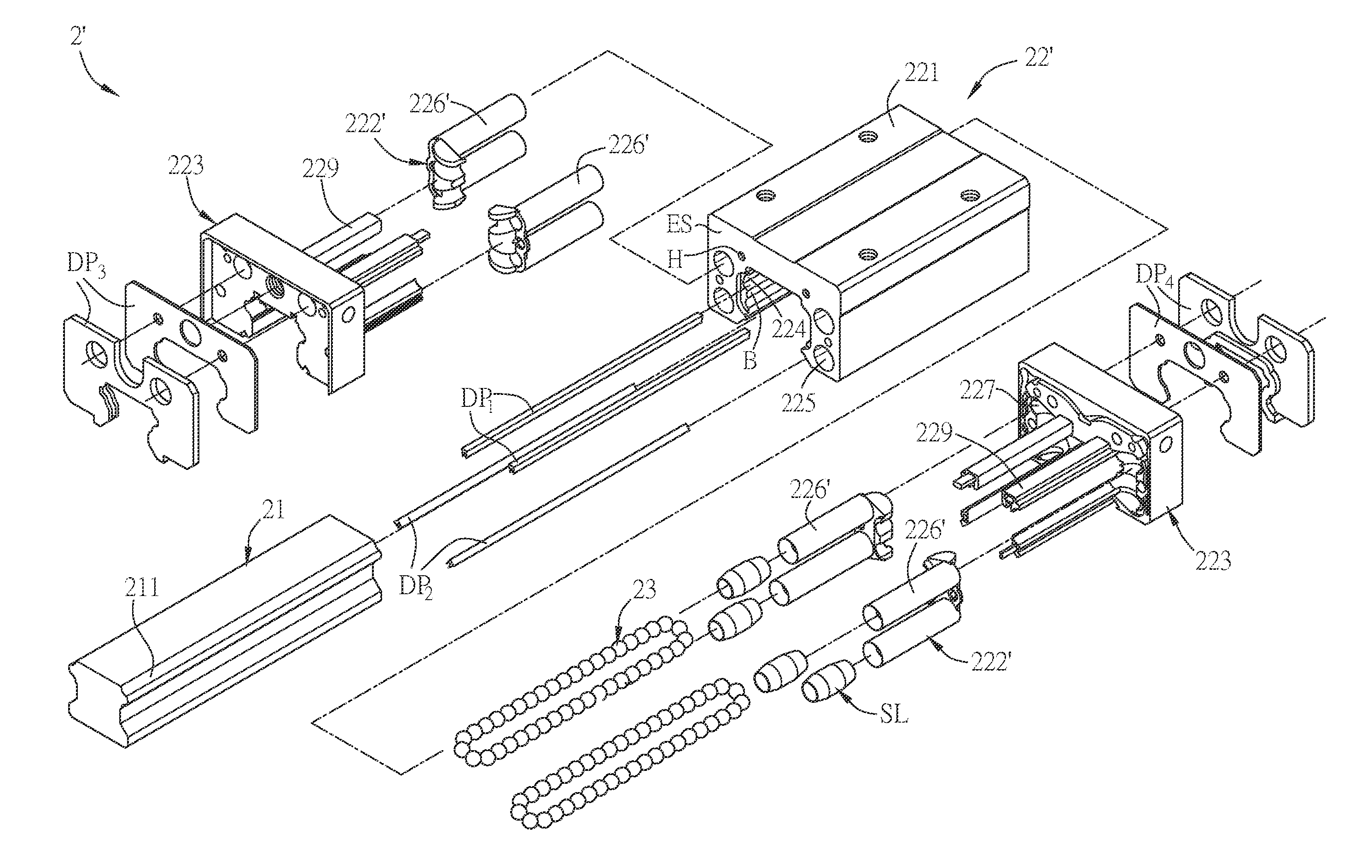
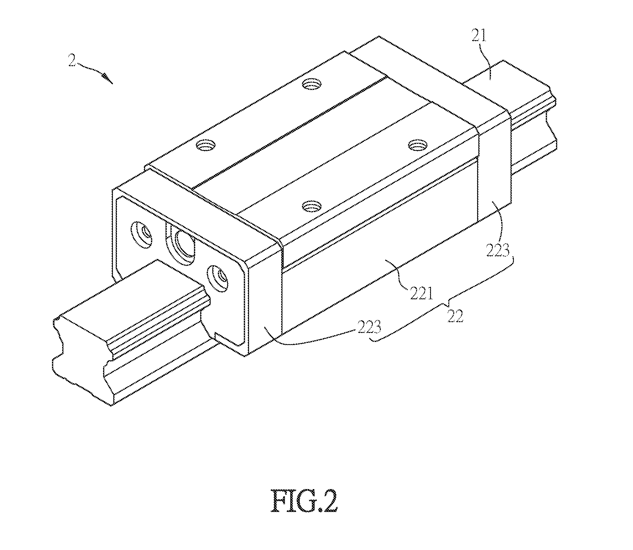
[0035]FIG. 2 is a schematic diagram of a linear motion module according to an embodiment of the invention, and FIG. 3 is a schematic exploded diagram of the linear motion module in FIG. 2. As shown in FIGS. 2 and 3, the linear motion module 2 includes a linear rail 21, a sliding block 22 and a plurality of balls 23. Each of two sides of the linear rail 21 is configured with at least a rail groove 211. The sliding block 22 is slidingly disposed on the linear rail 21, and includes a sliding block body 221, at least four circulation elements 222 and two end caps 223. The inside of the sliding block body 221 is configured with at least two inner circulation grooves 224. The inner circulation groove 224 and the rail groove 211 constitute an inner circulation passage. Besides, each of two s...


PUM


Abstract

A linear motion module comprises a linear rail, a sliding block and balls. The sliding block is slidingly disposed on the linear rail and comprises a sliding block body, circulation elements and end caps. The inside of the sliding block body is configured with inner circulation grooves, the inner circulation groove and the rail groove constitute an inner circulation passage, and each of two sides of the sliding block body is configured with at least a circulation channel that corresponds to the inner circulation passage and penetrates through the sliding block body. Each of the circulation elements includes at least a circulation tube, and the opposite two circulation tubes are connected to each other to constitute an outer circulation passage. Each of the end caps is configured with at least two circulation guiding grooves, and the circulation guiding groove is connected to the inner and outer circulation passages.

Description

BACKGROUND OF THE INVENTION[0001]1. Field of Invention[0002]The invention relates to a linear motion module.[0003]2. Related Art[0004]In the linear motion module, a ball circulation passage is disposed so that the sliding block can move frontward on the linear rail through the balls of a limited number. By the ball circulation passage, the balls can return to between the linear rail and the sliding block so as to function again after the sliding block moves.[0005]FIG. 1 is a sectional diagram of a conventional linear motion module. As shown in FIG. 1, the linear motion module 1 includes a linear rail 11, a sliding block 12 and a plurality of balls 13. The linear rail 11 is configured with a rail groove 111, the inside of the sliding block 12 is configured with an inner circulation groove 121, and the rail groove 111 and the inner circulation groove 121 constitute an inner circulation passage R for the balls moving through. Besides, the sliding block 12 is configured with an outer ci...

Claims


Application Information

Patent Timeline
Patent Type & Authority Patents(United States)
IPC IPC(8): F16C29/06F16C33/10F16C33/66
CPCF16C29/064F16C33/6696F16C29/0609F16C29/0611F16C29/0647F16C33/664
Inventor LEE, CHING-SHENGYANG, CHIN-TSAI
Owner TBI MOTION TECH CO LTD
Why Eureka
Try Eureka