Image forming apparatus, droplet discharge detecting method in the image forming apparatus, and computer program product

a technology of image forming apparatus and droplet discharge detection, which is applied in the direction of printing, inking apparatus, other printing apparatus, etc., can solve the problems of inability to properly perform image formation, inability to determine which nozzle does not have a defect, and too much time in detecting nozzle defects

Inactive Publication Date: 2015-04-28
RICOH KK
View PDF17 Cites 5 Cited by
  • Summary
  • Abstract
  • Description
  • Claims
  • Application Information

AI Technical Summary

Benefits of technology

[0010]It is an object of the present invention to at least partially solve the problems in the conventional technology.

Problems solved by technology

In a printing method described above, when a nozzle is clogged and fails to discharge the ink, an image formation cannot be properly performed.
However, the conventional method for detecting a nozzle defect by having each nozzle discharge an ink droplet one by one has the problem in that it takes too much time in detecting the nozzle defect in a situation where a high density and highly integrated head is produced.
The technology disclosed in Japanese Patent Application Laid-open No. 2006-110964 is capable of determining the number of ink droplets having been discharged simultaneously from a plurality of nozzles, but is incapable of determining which nozzle does have a defect.

Method used


Image

  • Image forming apparatus, droplet discharge detecting method in the image forming apparatus, and computer program product
  • Image forming apparatus, droplet discharge detecting method in the image forming apparatus, and computer program product
  • Image forming apparatus, droplet discharge detecting method in the image forming apparatus, and computer program product

Examples


Embodiment Construction

[0027]An embodiment is described in detail below with reference to the attached drawings.

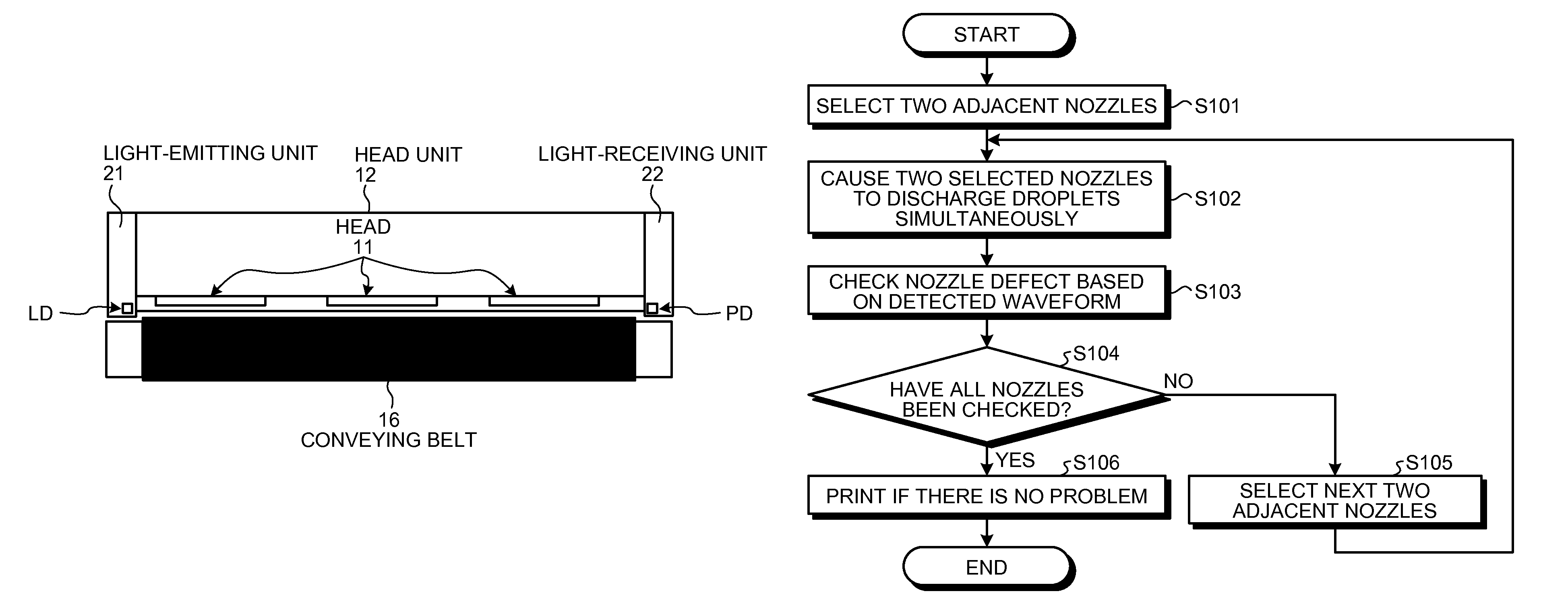
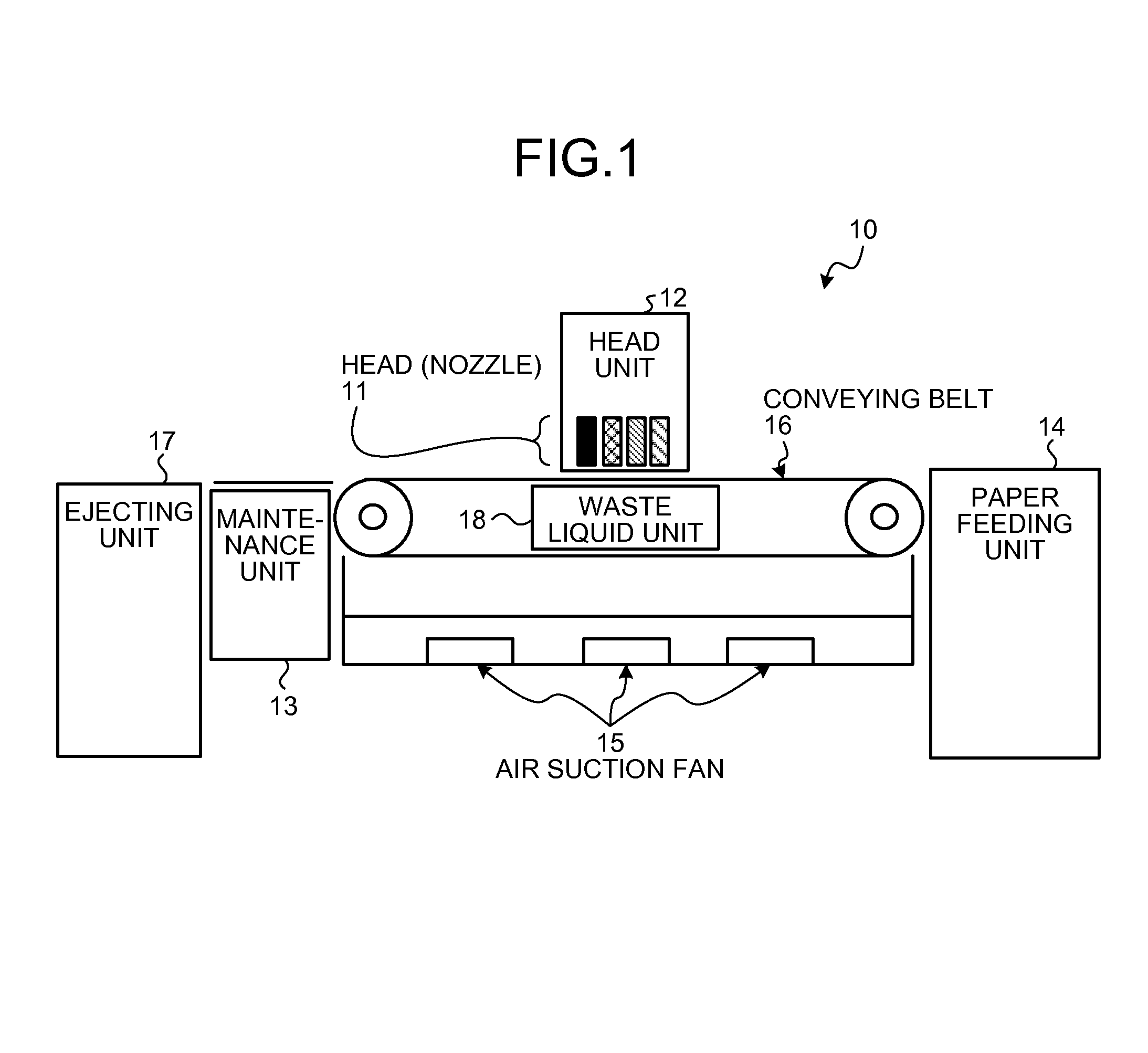
[0028]First, a schematic configuration of an inkjet recording device that includes a printing head provided along a line will be described with reference to FIG. 1. FIG. 1 is a diagram of an overall schematic configuration of an inkjet recording device having a printing head provided along a line.

[0029]An inkjet recording device 10 illustrated in FIG. 1 is also called a line printer. When printing, a plurality of print heads 11 (hereinafter referred to as heads 11) having a length that matches a printing width is fixed along a line to print on a recording sheet that has been conveyed thereto. In each of the heads 11, a plurality of nozzles for discharging ink is provided. The heads 11 mounted on a print head unit 12 (hereinafter referred to as a head unit 12) are usually provided in a staggered arrangement; however, a single unit as a linehead may be mounted instead thereon.

[0030]On the head uni...


PUM


Abstract

An image forming apparatus includes: a droplet discharging head that includes nozzle rows; a light emitting unit that irradiates a droplet with laser light emitted in a direction intersecting a discharging direction of the droplet; a light-receiving unit that receives scattered light scattered when the droplet is irradiated by the laser light and outputs a signal corresponding to an amount of the scattered light; and a droplet discharge detecting unit that detects a droplet discharging status of the nozzles based on the signal. The laser light is emitted with an optical axis shifted from middle between two adjacent nozzle rows; and the droplet discharge detecting unit selects two nozzles adjacent in a direction intersecting the nozzle rows as detection target nozzles, and detects the droplet discharging status of the detection target nozzles based on the scattered light scattered when droplets are simultaneously discharged from the detection target nozzles.

Description

CROSS-REFERENCE TO RELATED APPLICATIONS[0001]The present application claims priority to and incorporates by reference the entire contents of Japanese Patent Application No. 2011-046500 filed in Japan on Mar. 3, 2011.BACKGROUND OF THE INVENTION[0002]1. Field of the Invention[0003]The present invention relates to an image forming apparatus and a droplet discharge detecting method in the image forming apparatus.[0004]2. Description of the Related Art[0005]Generally, in inkjet recording devices, especially in a recording device provided with a head (linehead) as long as the width of paper, the head is not moved during printing and instead, a sheet of paper is conveyed directly beneath the head where ink is discharged onto the sheet so as to form an image thereon. In a printing method described above, when a nozzle is clogged and fails to discharge the ink, an image formation cannot be properly performed.[0006]Thus, there is a need to dissolve clogging in a nozzle and hence, detection of...

Claims


Application Information

Patent Timeline
Patent Type & Authority Patents(United States)
IPC IPC(8): B41J29/38B41J2/045B41J2/165
CPCB41J2/04581B41J2/0451B41J2/04561B41J2/16579B41J2/16588B41J2202/21
Inventor ONO, YASUKAZU
Owner RICOH KK
Why Eureka
Try Eureka