Automatic analyzer and method for using the same

a technology of automatic analyzer and analyzer, which is applied in the direction of chemical methods analysis, instruments, material analysis, etc., can solve the problems of user placing the reagent in the wrong place, human errors are more easily encountered, and the possibility is higher, so as to facilitate the change and preparation of reagents suitable for an operation mode, the effect of reducing the load on the user

Active Publication Date: 2015-06-23
HITACHI HIGH-TECH CORP
View PDF17 Cites 4 Cited by
  • Summary
  • Abstract
  • Description
  • Claims
  • Application Information

AI Technical Summary

Benefits of technology

[0010]An object of the present invention is to provide an automatic analyzer that is capable of reducing a user's workload required when a reagent is placed, and thereby facilitating change of the operation mode of the automatic analyzer.
[0019]According to the present invention, placement of reagents can be automatically changed. This makes it possible to reduce a load put on a user, which is caused by a change of the operation mode of an automatic analyzer.
[0020]Furthermore, according to the present invention, the change and preparation of reagents suitable for an operation mode can be facilitated.

Problems solved by technology

In the case of this method, with increase in the number of reagents placed in the reagent storing unit, human errors more easily occur.
For example, when the user places a reagent, there is a higher possibility that the user will place the reagent in the wrong place or the user will remove a necessary reagent.
In contrast to normal addition of a reagent, for example, when an operation mode is changed to another operation mode that requires transfer of many reagents from a refrigerator for storing reagents to the reagent storing unit of the analyzer, reagent placement work becomes more complicated.
As a result, an excessive load is put on the user.

Method used


Image

  • Automatic analyzer and method for using the same
  • Automatic analyzer and method for using the same
  • Automatic analyzer and method for using the same

Examples


Embodiment Construction

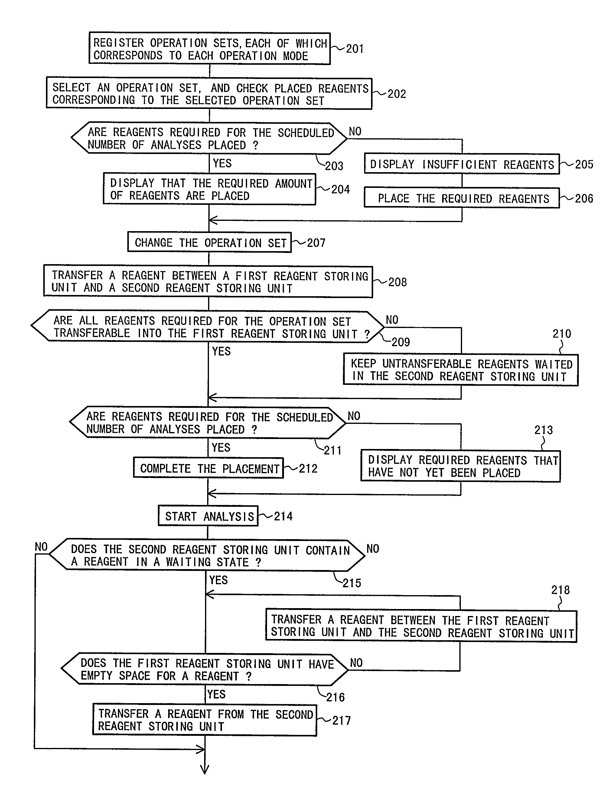
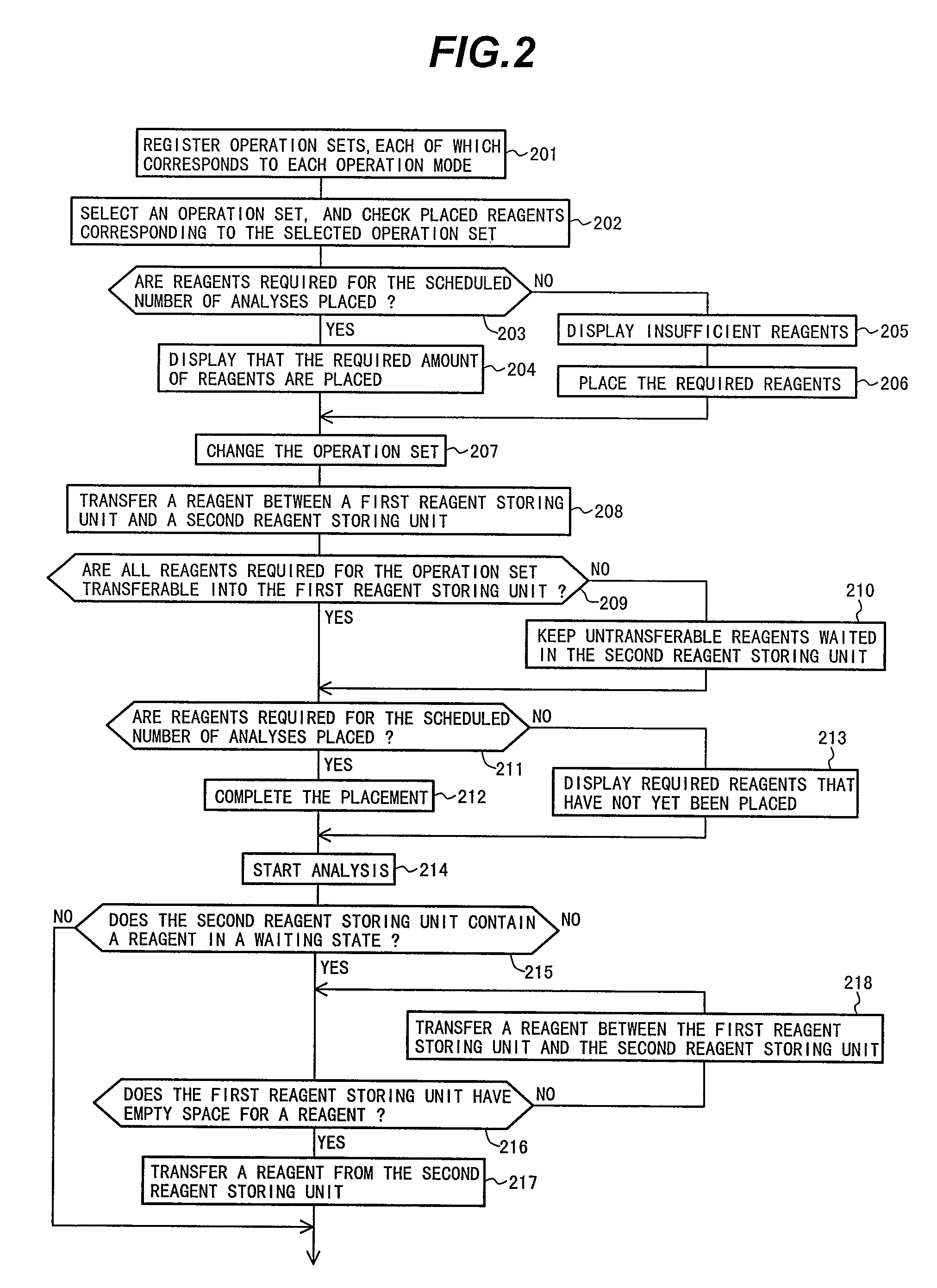
[0028]Embodiments of the present invention will now be described with reference to the accompanying drawings.

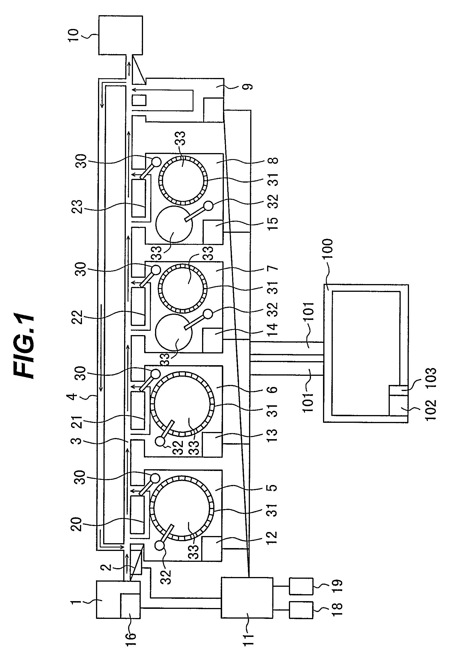
[0029]FIG. 1 is a diagram schematically illustrating the configuration of an automatic analyzer according to one embodiment of the present invention.

[0030]The automatic analyzer according to this embodiment includes a sample rack loading unit 1, an ID reading unit 2, a transfer line 3, a reexamination transfer line 4, analysis modules 5, 6, 7, and 8, a sample rack standby section 9, a sample rack collecting unit 10, a second reagent storing unit 100, and an overall control computer 11. The analysis modules 5, 6, 7, and 8 and the sample rack loading unit 1 are equipped with control computers 12, 13, 14, 15, and 16, respectively. In addition, the overall control computer 11 is equipped with an operation unit 18 and a display unit 19.

[0031]The sample rack loading unit 1 is a unit used to load a plurality of sample racks, each of which holds one or more samples (specimens). The a...


PUM

PropertyMeasurementUnit
timeaaaaaaaaaa
period of timeaaaaaaaaaa
night-time aaaaaaaaaa

Abstract

A method for an automatic analyzer to reduce a user's workload required when a reagent is placed therein, and thereby facilitating change of the operation mode of the automatic analyzer. The automatic analyzer including a first reagent storing unit that is capable of storing a plurality of reagent cassettes and a second reagent storing unit that is capable of storing a plurality of reagent cassettes. When the first reagent storing unit does not have empty space for a required reagent, and all reagents required for analysis operation for a selected operation set cannot be completely transferred to the first reagent storing unit, keeping the required reagent waiting in the second reagent storing unit. Further, when the first reagent storing unit is provided with empty space, the required reagent is transferred to the first reagent storing unit.

Description

BACKGROUND OF THE INVENTION[0001]1. Field of the Invention[0002]The present invention relates to an automatic analyzer for performing qualitative / quantitative analysis of a living body sample such as blood and urine and a method for using the automatic analyzer. The invention also relates to a computer program and a recording medium to which the program is written.[0003]2. Description of the Related Art[0004]In the field of automatic analysis, one analyzer may be used in various operation modes. For example, a limited number of items sometimes require multi-sample analysis at the time of a blood test in periodic medical examination. That is because the blood test does not require analyses covering many items. In such a case, reagents sufficient for the analysis of each item are placed in an analyzer so as to avoid the shortage of reagents during the multi-sample analysis that takes a long time to complete. In contrast to this, when the analyzer copes with requests for analyses cover...

Claims


Application Information

Patent Timeline
Patent Type & Authority Patents(United States)
IPC IPC(8): G01N35/02G01N21/00G01N35/10G01N35/00
CPCG01N35/1002Y10T436/11Y10T436/115831G01N2035/00673
Inventor YAGI, KENICHITAKAGI, YOSHIMITSUOHTAKE, HITOSHI
Owner HITACHI HIGH-TECH CORP
Why Eureka
Try Eureka