Device for fastening a marker device to a bone

a marker device and bone technology, applied in the field of devices for fastening markers to bones, can solve the problems of increasing the length of time that patients have to spend in the operating theatr

Active Publication Date: 2015-08-04
BRAINLAB
View PDF25 Cites 7 Cited by
  • Summary
  • Abstract
  • Description
  • Claims
  • Application Information

AI Technical Summary

Benefits of technology

[0018]In another embodiment, the helical spring is fitted onto the abutment element, wherein the abutment element preferably extends through the spring, into the fixing element. The screw passes, preferably concentrically, through the abutment element, the helical spring and the fixing element. In this embodiment, the fixing element, the abutment element and the spring constitute an easy-to-handle unit which can be fixed to the bone in a single working step.
[0019]The fixing element is then for example designed to be sleeve-like, i.e. the f

Problems solved by technology

One of the disadvantages of this fastening device is that attaching it to the bone requires a large number of steps

Method used


Image

  • Device for fastening a marker device to a bone
  • Device for fastening a marker device to a bone
  • Device for fastening a marker device to a bone

Examples


Embodiment Construction

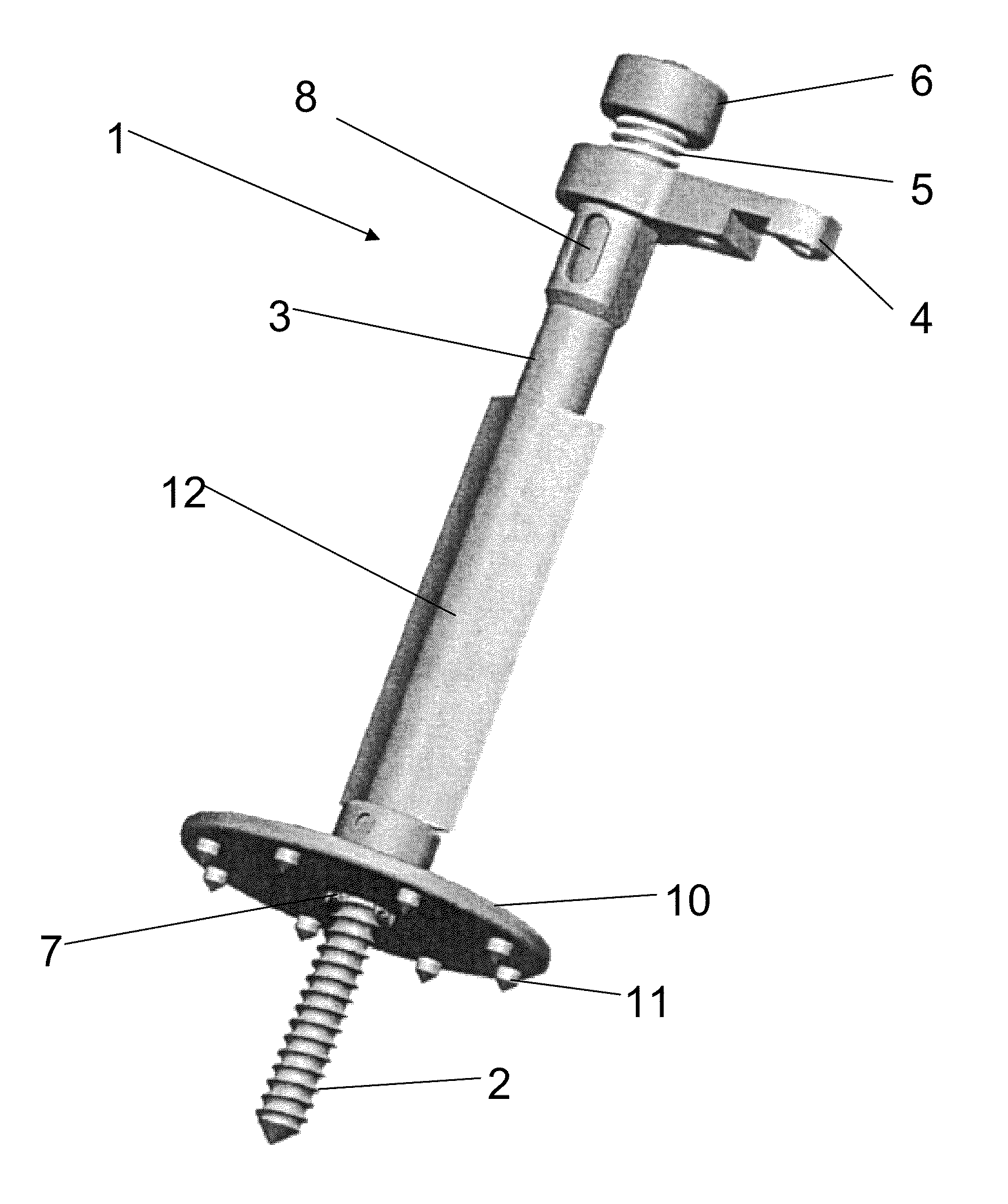
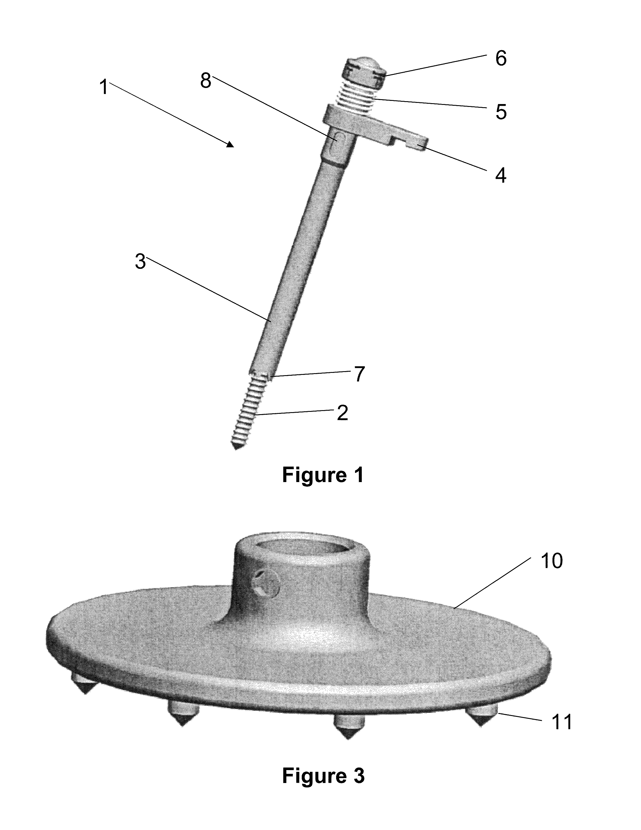
[0032]FIG. 1 shows a device 1 for fastening a marker device in a bone, in accordance with a first design. For the sake of clarity, both the marker device and the bone have been omitted in all the figures.

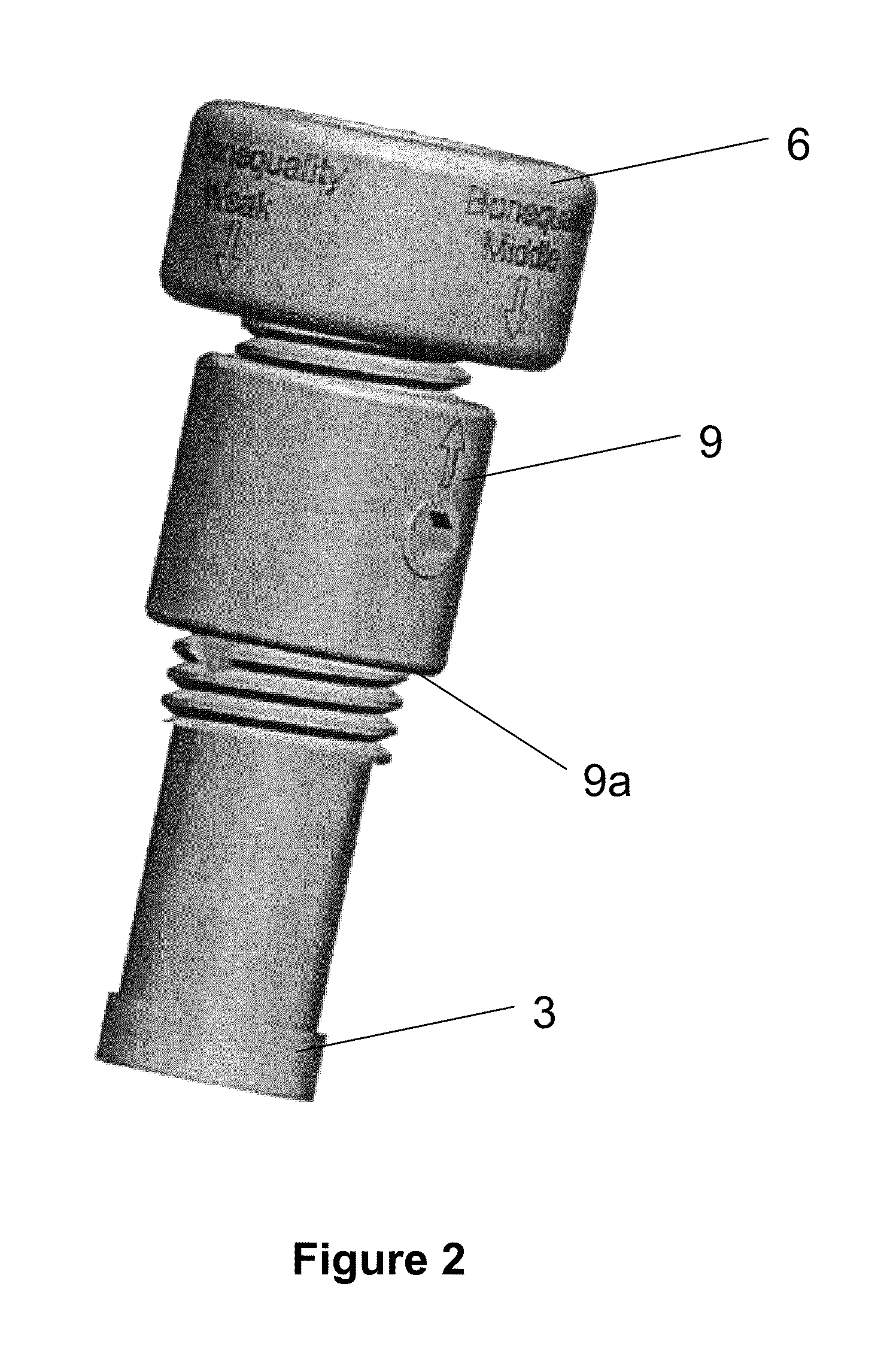
[0033]The device 1 comprises a fixing element 3 and a mounting 4 for the marker device on the fixing element 3. The fixing element 3 is embodied to be sleeve-like, i.e. it comprises a hollow-cylindrical base body. On one facing area of the hollow-cylindrical base body, the fixing element 3 comprises spikes 7 which penetrate into the bone when the device 1 is attached and prevent the fixing element 3 from rotating relative to the bone. A spring 5 abuts the opposite facing area of the fixing element 3 and also abuts an abutment. The abutment is formed by an area of an abutment element 6 which can be telescopically shifted relative to the fixing element 3 in the axial direction of the hollow-cylindrical base body, and one end of which enters the fixing element 3 through the spring 5.

[0...


PUM


Abstract

A device for fastening a marker device to a bone, comprising a fixing element including a mounting for the marker device, comprising a spring designed to contact an abutment for exerting a force between the abutment and the fixing element in the direction of the bone.

Description

RELATED APPLICATION DATA[0001]This application claims the priority of U.S. Provisional Application No. 61 / 116,774, filed on Nov. 21, 2008, which is hereby incorporated in its entirety by reference.FIELD OF THE INVENTION[0002]The present invention relates to a device for fastening a marker device to a bone, comprising a fixing element and a mounting for the marker device on the fixing element.BACKGROUND OF THE INVENTION[0003]In image-guided operations, it is necessary to provide objects such as bones or medical instruments with marker devices. A marker device consists for example of one or more reflective spheres which can be detected by sensors. The position of the marker device and therefore the position of the object can be determined from the position of the spheres with respect to each other.[0004]One commercially available device for fastening a marker device to a bone consists of a screw, a clamping device, an adjusting screw and a sleeve which comprises a mounting for the mar...

Claims


Application Information

Patent Timeline
IPC IPC(8): A61B19/00
CPCA61B19/54A61B19/5244A61B2019/5416A61B2019/5483A61B2019/5491A61B2019/5487A61B2090/3983A61B2090/3916A61B2090/3991A61B34/20A61B90/39A61B2090/3987
Inventor PLA.BETA.KY, NORMANMILLAHN, MANUELWARKENTINE, BLAINE
Owner BRAINLAB
Why Eureka
Try Eureka