Check patentability & draft patents in minutes with Patsnap Eureka AI!

Selectively calibrated work piece cutting guide

a work piece and cutting guide technology, applied in the direction of work benches, measurement devices, instruments, etc., can solve the problems of circular saws that are difficult and dangerous to use, the cutting of circular saw blades is not always accurate, and the cutting is difficult and dangerous

Inactive Publication Date: 2016-01-12
SHERMAN GARY
View PDF66 Cites 5 Cited by
  • Summary
  • Abstract
  • Description
  • Claims
  • Application Information

AI Technical Summary

Benefits of technology

The apparatus enhances user safety by preventing kick-up and kickback, ensures accurate cuts, and simplifies the cutting process by eliminating the need for constant recalibration and additional marking steps.

Problems solved by technology

Circular saws can be difficult and dangerous to use for a number of reasons.
This further requires the user to place his or her abdomen, waist, leg and / or thigh closer to the circular saw blade, while simultaneously concentrating on keeping the cutting guide on a line that was previously drawn on the work piece, to result in a somewhat even, but not necessarily accurate, cut.
As one of Popular Mechanics magazine's top five most dangerous tools, the circular saw's blade travels at 120 miles per hour and is a major cause of injury, especially to “do-it-yourselfers.” Although professional carpenters might be more prepared to handle the hazards of using a circular saw due to their experience with the tool, even carpenters suffer from daily fatigue that increases as the long workday progresses, as well as exposure to the elements of a typical outdoor or construction-site work environment.
These factors contribute to the likelihood of accidental injury from circular saw use, even among experienced users.
Circular-saw kick-up and kickback can be a dangerous problem.
Similarly, kickback occurs when the circular blade of a power saw binds or grabs a work piece being cut, which throws the spinning saw and its cutting blade back toward the user.
The motion of kick-ups and kickbacks can occur so quickly as to make it difficult or impossible for the user to avoid injury.
Although various guides for circular saws are known, none of these guides provide protection for the user from kick-ups and kickbacks.
Disadvantageously, this procedure adds an extra step that slows the cutting process, and further, the '978 patent does not specifically address the potential for harm to the user due to kick-up, kickback, or other safety concerns.
This scenario provides little protection from circular saw kick-up and kickback and increases the user's exposure to the moving blade.
Further, although the tool guide of the '978 patent has an integrated tape measure with means for adjusting the effective extension length of the tape with respect to the guide, this arrangement can be unreliable because the tape adjustment assembly is pulled against the work piece each time the device is used.
This pulling of the tape adjustment assembly promotes and repeatedly increases the potential for inaccuracy due to loss of calibration.
Also, since most users do not own multiple circular saws, adjustability of the tool guide can be more of a detriment than a benefit, due to this constant recalibration necessitated by a number of moving parts.
Unless the device is made to be extremely large, passing a circular saw adjacent to the device can be difficult.
This is because the tape-measure mounting device is stationary and centrally positioned within the device, thereby providing insufficient clearance for a circular saw motor to pass by the mounted tape measure.
The '710 patent provides no means for positioning the tape measure further away from the circular saw in a way that provides the necessary clearance.
The size limitation of the device that is necessary to make the device portable and easy to carry limits the length of material that can be cut, making the cutting of commonly-available building material (for example, 2″×4″ framing lumber in 6- to 16-foot lengths) impractical.
Moreover, the '389 application discloses a device for cutting a workpiece at various angles that limits the length of material being cut, making the cutting of commonly-available building material (for example, 2″×4″ framing lumber in 6- to 16-foot lengths) impractical.

Method used


Image

  • Selectively calibrated work piece cutting guide
  • Selectively calibrated work piece cutting guide
  • Selectively calibrated work piece cutting guide

Examples


Embodiment Construction

[0019]Reference herein to “one embodiment” or “an embodiment” means that a particular feature, structure, or characteristic described in connection with the embodiment can be included in at least one embodiment of the invention. The appearances of the phrase “in one embodiment” in various places in the specification are not necessarily all referring to the same embodiment, nor are separate or alternative embodiments necessarily mutually exclusive of other embodiments. The same applies to the term “implementation.”

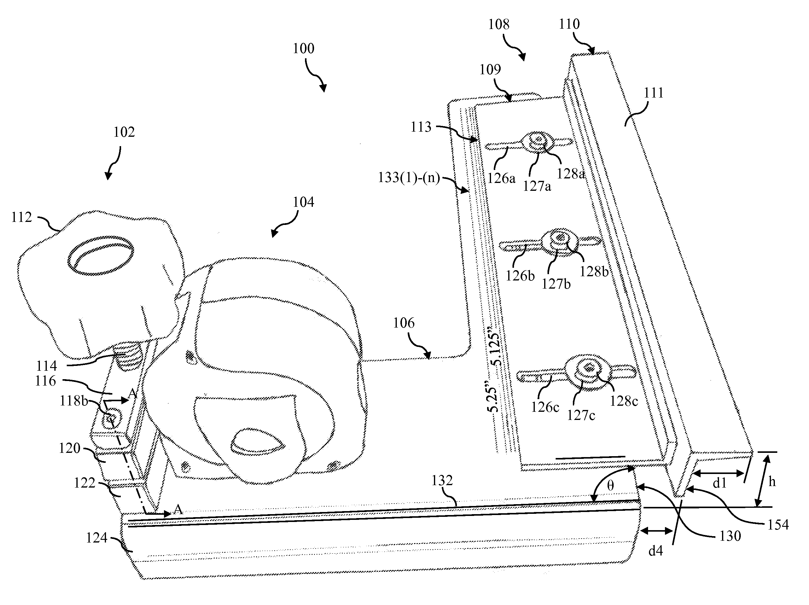
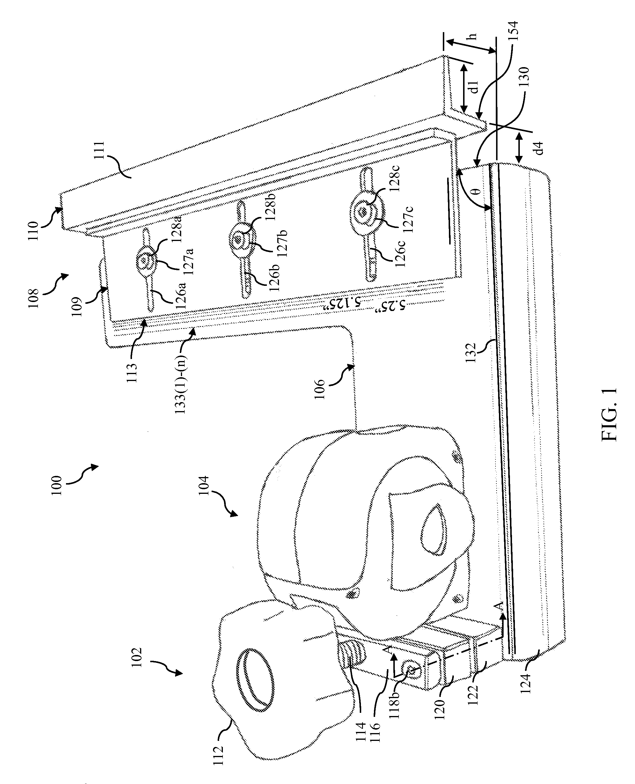
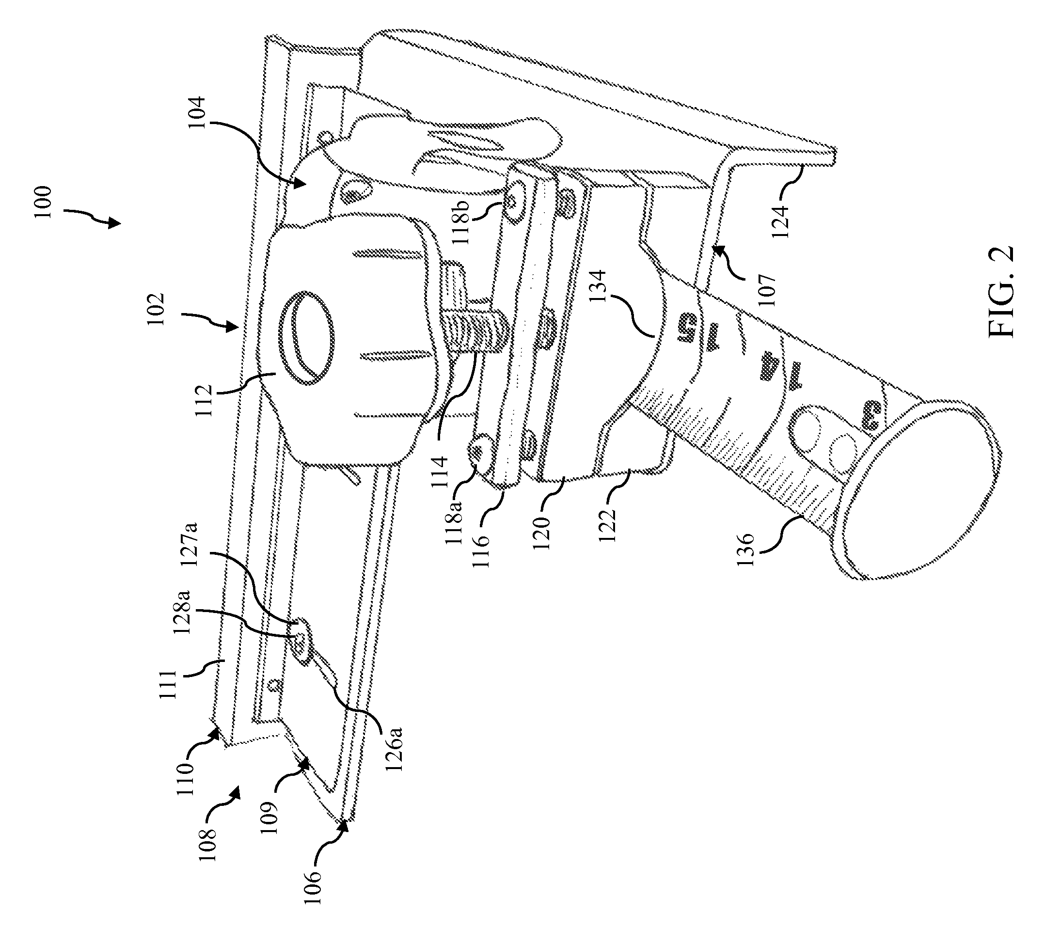
[0020]In the following description, it will be understood that certain embodiments of the present invention are directed to work-piece cutting guides that can be calibrated for use with differently-sized cutting instruments by adjusting a dimension of the cutting guide. Although, a specific embodiment is described below as using a movable fence to adjust the calibrating dimension, embodiments of the present invention are not so limited. According to alternative embodiments ...


PUM


Abstract

In one embodiment, an apparatus guides movement of a cutting instrument across a first surface of a work piece. The apparatus has a base, a tape-measure mount, and a fence. The base has a substantially-flat lower surface that abuts the first surface of the work piece. The tape-measure mount mounts a tape measure to the base on a first side of the apparatus. The fence is attached to the base, opposite the first side of the apparatus, and has a guiding surface that guides the movement of the cutting instrument across the first surface of the work piece. At least one movable component, other than a tape measure tape, is attached to the base to permit adjustment of a dimension of the apparatus that is used to calibrate the apparatus for use with the cutting instrument.

Description

CROSS-REFERENCE TO RELATED APPLICATIONS[0001]This application claims the benefit of the filing date of U.S. provisional application No. 61 / 813,812, filed on Apr. 19, 2013, the teachings of all of which are incorporated herein by reference in their entirety.[0002]The subject matter of this application is related to U.S. provisional application No. 61 / 439,406, filed on Feb. 4, 2011, U.S. non-provisional patent application Ser. No. 13 / 365,552 filed on Feb. 3, 2012, and PCT patent application no. PCT / US12 / 23764 filed on Feb. 3, 2012, the teachings of all of which are incorporated herein by reference in their entirety.BACKGROUND OF THE INVENTION[0003]1. Field of the Invention[0004]The present invention relates to the measurement and cutting of work pieces, and, more specifically but not exclusively, to apparatuses that may be used to guide movement of a cutting instrument, such as a circular saw, across a work piece at a desired measurement from an edge of the work piece.[0005]2. Descrip...

Claims


Application Information

Patent Timeline
Patent Type & Authority Patents(United States)
IPC IPC(8): G01B3/10B25H1/00
CPCB25H1/0078G01B3/1084G01B2003/1089G01B3/1089
Inventor SHERMAN, GARY
Owner SHERMAN GARY
Features
  • R&D
  • Intellectual Property
  • Life Sciences
  • Materials
  • Tech Scout
  • Unparalleled Data Quality
  • Higher Quality Content
  • 60% Fewer Hallucinations
Learn More