Electromagnetic actuating device with ability for position detection of an armature

a technology of armature and actuation device, which is applied in the direction of magnets, propulsion systems, magnetic bodies, etc., can solve the problems of insufficient space for external position sensors, measurement methods cannot be easily converted, and the friction coefficient of the guide and/or mounting of the armature within the inside space of the coil can be reduced, and the overall volume of the control device is small.

Active Publication Date: 2016-03-29
ZF FRIEDRICHSHAFEN AG
View PDF10 Cites 4 Cited by
  • Summary
  • Abstract
  • Description
  • Claims
  • Application Information

AI Technical Summary

Benefits of technology

[0012]Because of the dual use of the coil both for position displacement and position detection, compared with a control device without position detection ability, the fitting volume required by the control device according to the invention is hardly any different. The axial separation zone between two adjacent part-coils can be made very narrow and therefore entails only a comparatively small additional volume. Consequently, notwithstanding its ability to detect the position of the armature, the electromagnetic control device according to the invention can be made very compact.
[0025]A further objective of the invention is to indicate an operating method for a control device by means of which the position of an armature can also be determined in a simple and space-saving manner.

Problems solved by technology

In particular because of this preferred choice of material, the measurement method cannot easily be converted for determining the position of a longitudinally movable, ferromagnetic armature of an electromagnetic control device.
This again requires a relatively large fitting volume.
In many applications, moreover, the space needed for the external position sensor is not available.
Thus, the inside coil space of the main coil must provide extra space for the separate sensor coil, and this increases the overall fitting volume of the control device.

Method used


Image

  • Electromagnetic actuating device with ability for position detection of an armature
  • Electromagnetic actuating device with ability for position detection of an armature
  • Electromagnetic actuating device with ability for position detection of an armature

Examples


Embodiment Construction

[0038]In FIGS. 1 to 8 corresponding parts are given the same indexes. Details of the example embodiments explained more fully below can also, in their own right, be regarded as an invention or can be part of the object of an invention.

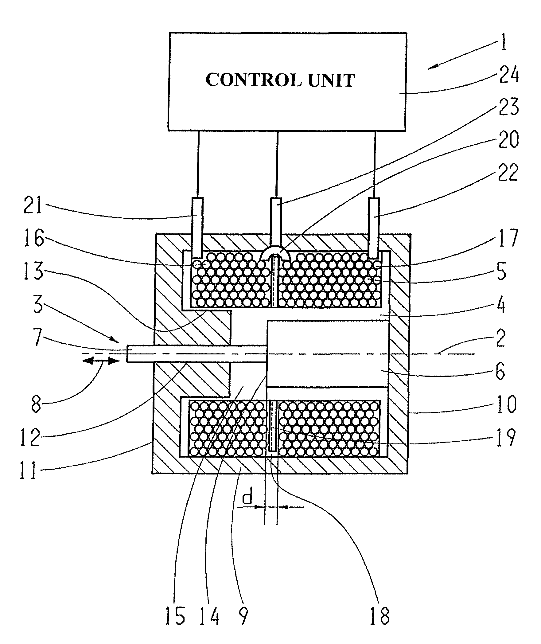
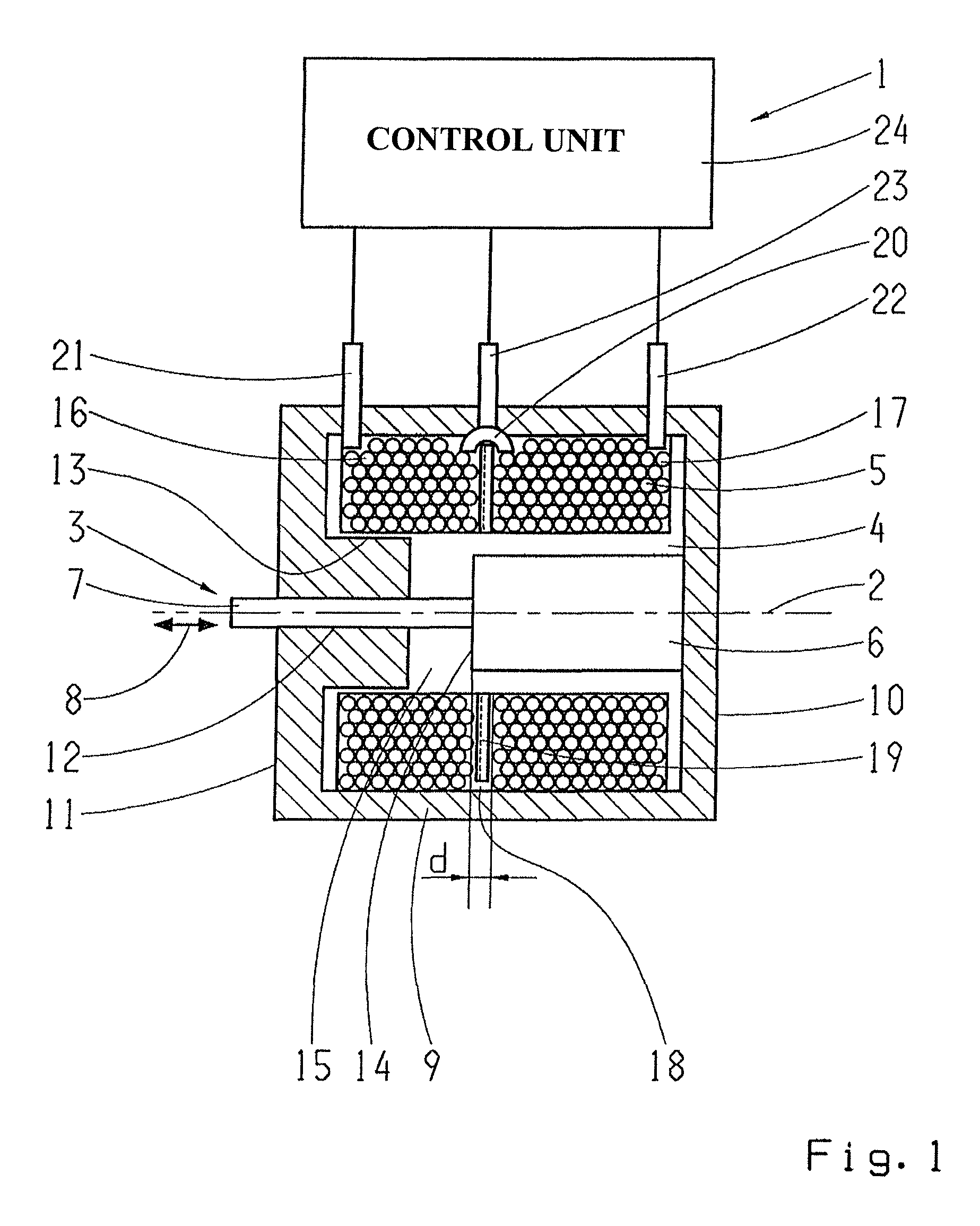
[0039]FIG. 1 shows an electromagnetic control device 1 which comprises a control element 3 that can move along a central longitudinal axis 2 and that is arranged at least partially within the coil inside space 4 of an electric coil 5. The longitudinally moving control element 3 comprises an armature 6 and a control rod 7. In particular, as part of the control element 3 the armature 6 is within the inside space 4 of the coil. The longitudinal mobility of the control element 3 is indicated by the double arrow 8.

[0040]The coil 5 is arranged in a housing that comprises an approximately cylindrical outer shell 9 and axial end covers 10 and 11. The end cover 11 has an opening 12 through which the control rod 7 passes to the space outside the housing. On the ...


PUM

PropertyMeasurementUnit
movement currentaaaaaaaaaa
axial areaaaaaaaaaaa
current-carrying capacityaaaaaaaaaa

Abstract

An electromagnetic control device has a coil with a central axis and an interior space, and a control element that moves along the axis and is arranged at least partially within an interior space of the coil. The control element comprises an armature that axially moves to a desired position when the coil is energized. The coil is divided into at least two separate portions that are arranged axially behind one another and connected electrically in series with one another. An electric central tap is provided, between two adjacent coil portions, by which a sensor current, provided for determining an axial position of the armature, can be fed into a subset of the coil portions. When the armature is in a defined axial position, an axial end face of the armature is located within an axial area determined by an axial separation zone provided between two adjacent coil portions.

Description

[0001]This application claims priority from German patent application serial no. 10 2012 204 321.7 filed Mar. 19, 2012.FIELD OF THE INVENTION[0002]The invention concerns an electromagnetic control device with an electric coil that has a central longitudinal axis and surrounds an inside space of the coil, and with a control element which is arranged at least partially in the inside space of the coil and can move along the central longitudinal axis.BACKGROUND OF THE INVENTION[0003]An electromagnetic control device of that type can be an actor. Other terms commonly used in control technology for an actor are actuator, control motor and / or lifting magnet. Such a component serves, for example, for driving or moving valves or flaps to control the flow of gaseous or liquid media. A possible field of use in this case is automotive technology.[0004]For accurately timed actuation of the control device a knowledge of the position of the control element, or the armature which is part of the con...

Claims


Application Information

Patent Timeline
Patent Type & Authority Patents(United States)
IPC IPC(8): H02K11/00H01F7/16H01F7/18
CPCH02K11/25H01F7/1607H01F7/1844H01F2007/1692H01F2007/185
Inventor WEINL, FLORIANLINDER, MICHAEL
Owner ZF FRIEDRICHSHAFEN AG
Why Eureka
Try Eureka