Chain tensioner

a chain tensioner and chain technology, applied in the direction of belts/chains/gearrings, mechanical instruments, belts/chains/gears, etc., can solve the problems of difficult universal use of the tensioner, difficulty in adjusting the tensioner, so as to achieve a wider range of flow resistance, simplify the structure, and reduce the effect of friction

Active Publication Date: 2016-04-05
TSUBAKIMOTO CHAIN CO
View PDF9 Cites 3 Cited by
  • Summary
  • Abstract
  • Description
  • Claims
  • Application Information

AI Technical Summary

Benefits of technology

[0021]The present invention is directed to solve these problems, and aims to provide a chain tensioner that has a simple structure, is universally usable, is capable of supplying sufficient and necessary oil when restarted after a long time after the stop of oil supply, enables reduction in entire length and size, and enables easy production and reduction in production cost.

Problems solved by technology

However, this configuration cannot be applied to a design in which oil is supplied laterally.
Universal use of the tensioner was difficult because of the restrictions on the position of the oil supply hole (oil supply hole 122) or mounting orientation of the chain tensioner.
Another problem was that the plunger structure was made complex because of the anti-rotation mechanism that was essential to stop rotation of the plunger.
The production process was therefore complex because the plunger needed machining in many parts, and also the cost was increased because of material limitations.

Method used


Image

  • Chain tensioner
  • Chain tensioner
  • Chain tensioner

Examples


first embodiment

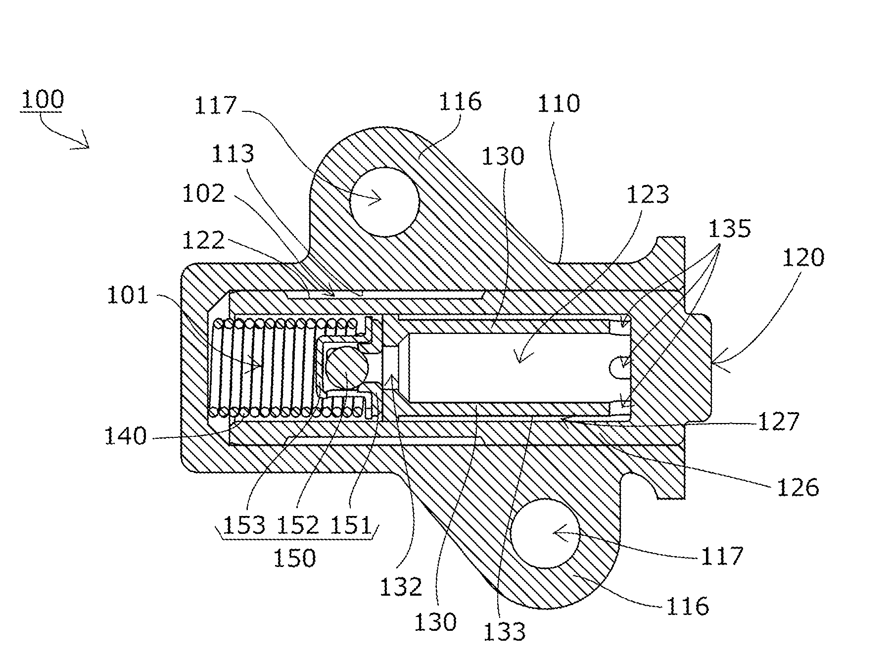
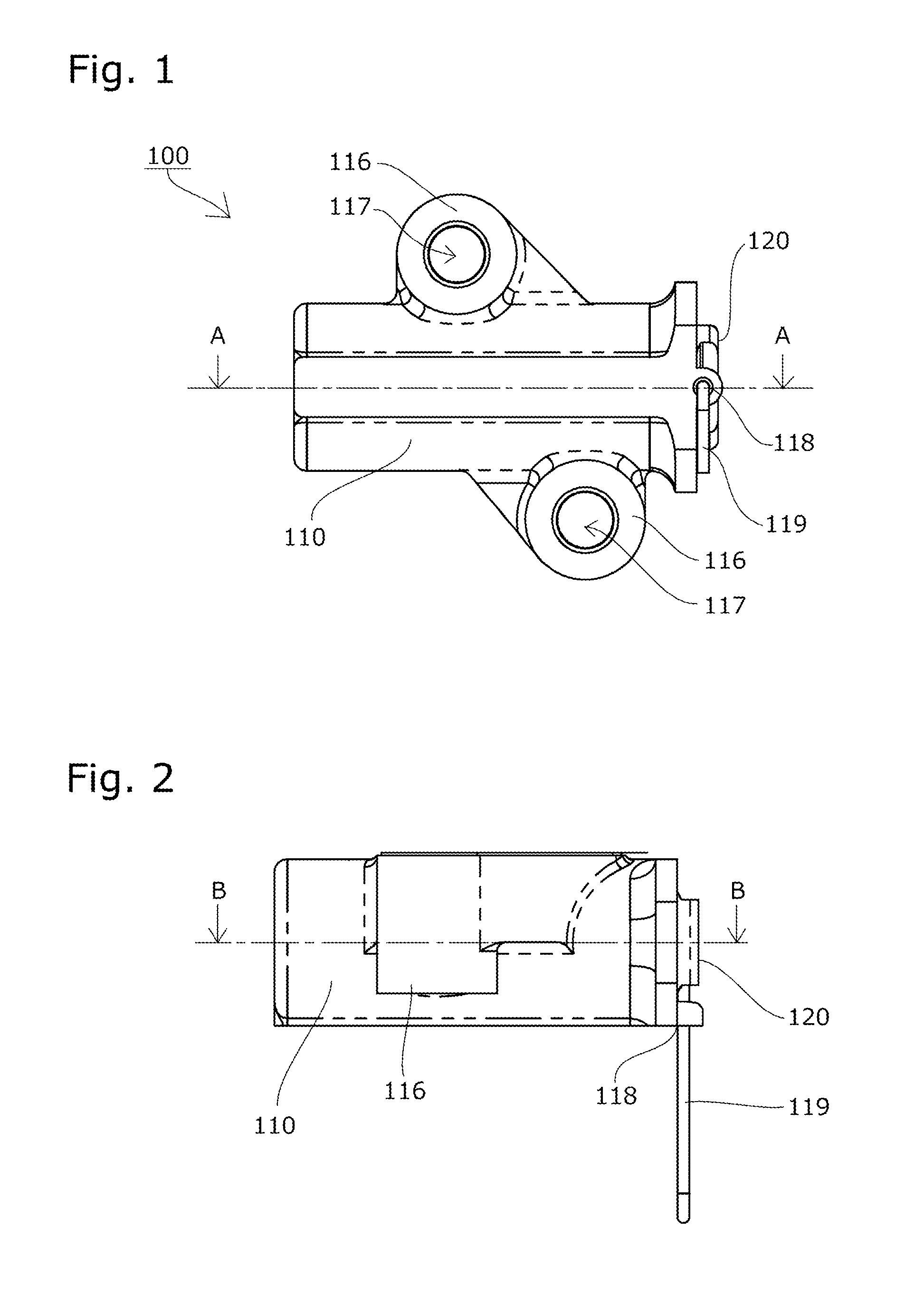
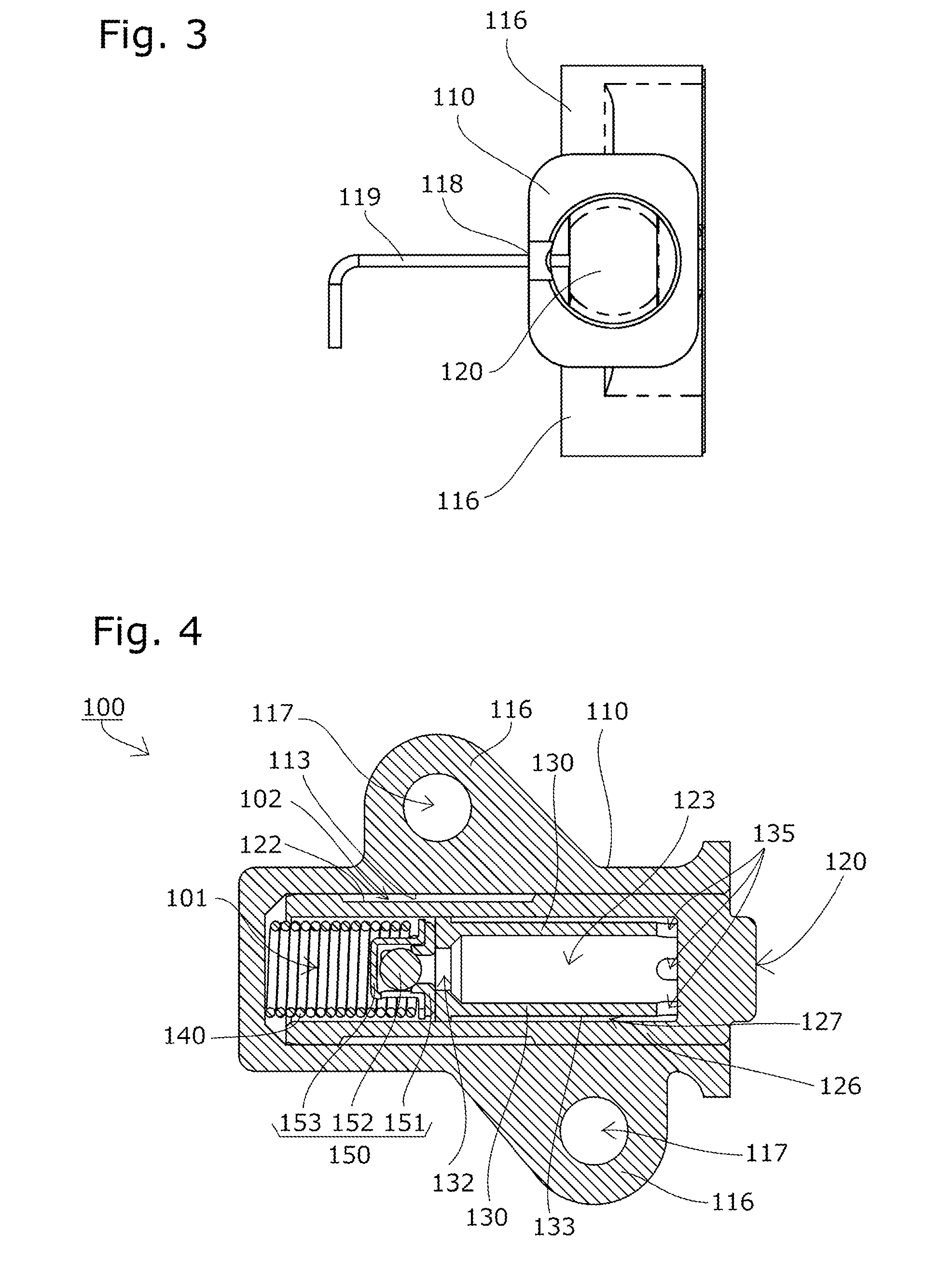
[0062]A chain tensioner 100 according to the present invention will be described with reference to the drawings.

[0063]The chain tensioner 100 according to a first embodiment of the present invention includes, as shown in FIG. 1 to FIG. 8, a tensioner body 110 having a cylindrical plunger bore 111 with an open end, a cylindrical plunger 120 slidable within the plunger bore 111, and a coil spring 140 that is an urging unit accommodated inside an oil pressure chamber 101 formed between the plunger bore 111 and the rear end of the plunger 120 such as to be able to expand and contract and to urge the plunger 120 outward.

[0064]The chain tensioner 100 according to this embodiment is securely mounted inside an engine having a chain guide mechanism. For this purpose, the tensioner body 110 has mounting parts 116 with mounting holes 117 for bolts or the like to pass through as shown in FIG. 1 to FIG. 6.

[0065]An oil supply hole 114 is formed in the cylindrical surface 113 of the plunger bore 1...

third embodiment

[0123]End face leak grooves 137 and seat leak grooves 154 similarly to the third embodiment may be provided instead of the inner leak grooves (not shown).

[0124]While specific examples of the chain tensioner according to the present invention have been described in the embodiments above, the chain tensioner according to the present invention is not limited to these examples, and the shapes, positions, sizes, and positional relationships with each other of various constituent parts may be changed in various manners.

[0125]For example, while the connection / adjustment groove 122 or the body-side connection / adjustment groove 103 extends all around in the embodiments described above so that the supply chamber 102 is tubular, the connection / adjustment groove 122 or the body-side connection / adjustment groove 103 may be formed only in part (in such a shape as, for example, the connection / adjustment groove 123 of Japanese Patent Publication No. 4376278 mentioned above), so that the supply cham...


PUM


Abstract

To provide a chain tensioner that has a simple structure, is universally usable, is capable of supplying sufficient and necessary oil when restarted after a long time after the stop of oil supply, enables reduction in entire length and size, and enables easy production and reduction in production cost. An urging unit 140 provided in an oil pressure chamber 101 to be expandable and contractible urges a plunger 120 outward from a plunger bore 111 in a tensioner body 110 of the chain tensioner 100. The plunger 120 includes a plunger body 126, a check valve 150 provided inside the body, and a reserve tube 130 that has an oil reservoir chamber 123 communicating with the oil pressure chamber 101 through an oil hole 132.

Description

BACKGROUND OF THE INVENTION[0001]1. Field of the Invention[0002]The present invention relates to a chain tensioner that includes a tensioner body having a cylindrical plunger bore with an open end, a cylindrical plunger slidable within the plunger bore, and an urging unit accommodated inside an oil pressure chamber formed between the plunger bore and the rear end of the plunger such as to be able to expand and contract and to urge the plunger outward, the chain tensioner being capable of maintaining suitable tension of a chain.[0003]2. Description of the Related Art[0004]Chain tensioners are commonly used for maintaining suitable tension of chains. In a chain guide mechanism that slidably guides a transmission chain such as an endless roller chain passing over respective sprockets of a crankshaft and a cam shaft inside an engine room with a guide shoe, for example, it is known to urge a pivoting chain guide having the guide shoe with a chain tensioner to maintain suitable tension.[0...

Claims


Application Information

Patent Timeline
Patent Type & Authority Patents(United States)
IPC IPC(8): F16H7/08
CPCF16H7/08F16H7/0848F16H2007/0806F16H2007/0812F16H2007/0859F16H2007/0878F16H2007/0891
Inventor KUREMATSU, YUJI
Owner TSUBAKIMOTO CHAIN CO
Why Eureka
Try Eureka