Portable hand rehabilitation device

a hand rehabilitation and portability technology, applied in the field of rehabilitation devices, can solve the problems of brain damage, increased damage, and limited motor function of many individuals in the united states, and achieve the effect of prolonging the battery li

Active Publication Date: 2016-05-03
UNIV OF TENNESSEE RES FOUND
View PDF14 Cites 19 Cited by
  • Summary
  • Abstract
  • Description
  • Claims
  • Application Information

AI Technical Summary

Benefits of technology

[0022]Preferably, the therapeutic device also has a power switch. The power switch allows the patient or a health care assistant to manually activate and de-activate the controller and micro-motors. This extends battery life. In addition, the therapeutic device also preferably includes a light source. The light source is arranged on the housing to deliver visual input to the patient when a micro-motor is vibrating.

Problems solved by technology

Many individuals in the United States suffer from limited motor function in their extremities.
When blood fails to get through the brain, the oxygen supply to the affected area is cut of, causing brain cells to die.
The longer the brain is without blood, the more severe the damage will be.
This produces bleeding into the brain matter, causing damage to surrounding brain cells.
Individuals may also lose function in one or more extremities as a result of an injury.
Such injuries may occur due to a car accident, a diving accident, a fall, or other trauma.
In these instances, the individual's cervical spine and nerves may be injured, again producing paresis in the hands.
Additionally, such trauma can produce brain injury.
Finally, some individuals may suffer some degree of paresis due to brain injury caused by an explosion or accident incident to work or military duty.
Such individuals have difficulty performing routine tasks such as eating, turning off a light, manipulating a remote control, typing, or countless other activities that most people take for granted.
Such therapy tends to be expensive.
However, home-based programs are sometimes limited by the motivation of the patient and the patient's desire or ability to use proper techniques.

Method used


Image

  • Portable hand rehabilitation device
  • Portable hand rehabilitation device
  • Portable hand rehabilitation device

Examples


Embodiment Construction

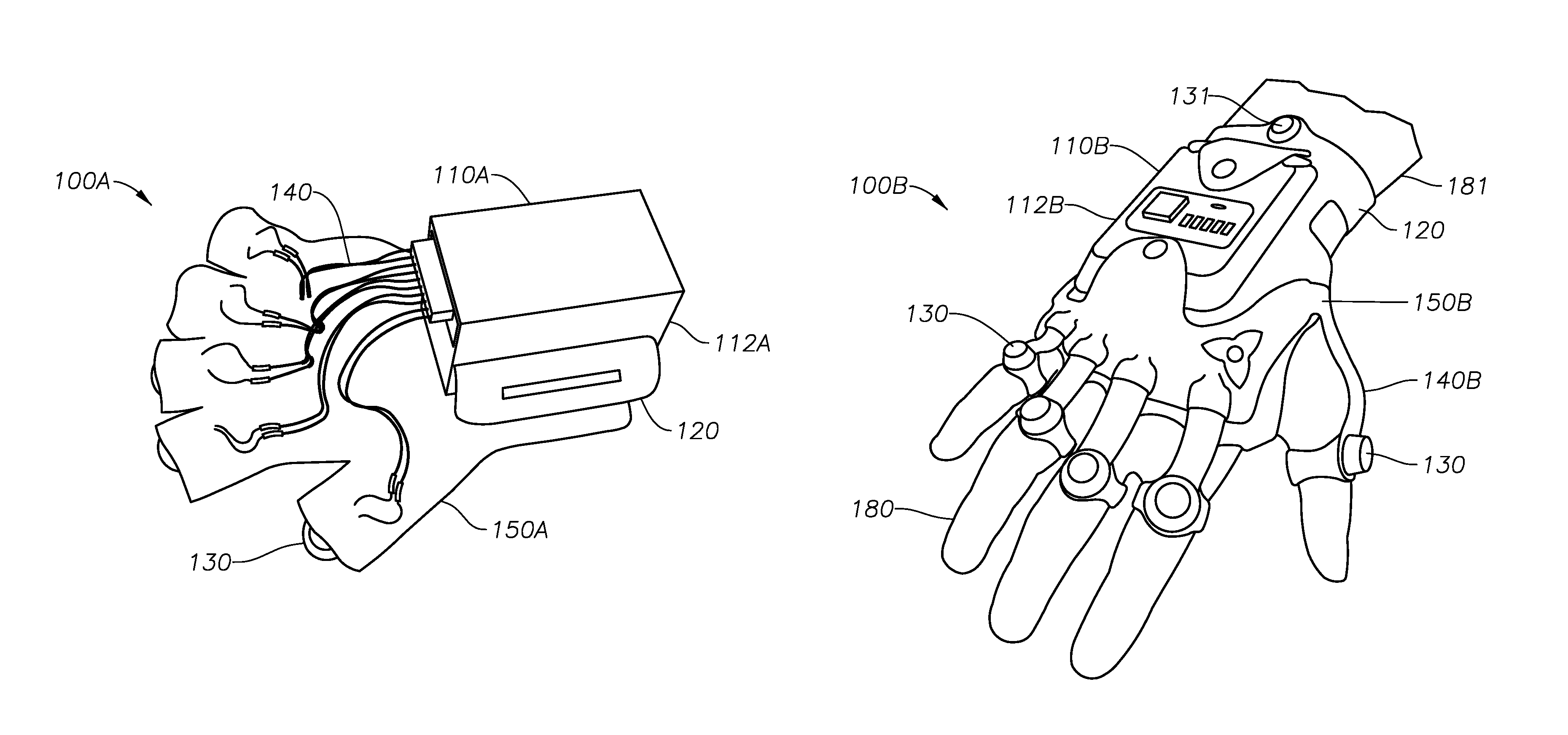
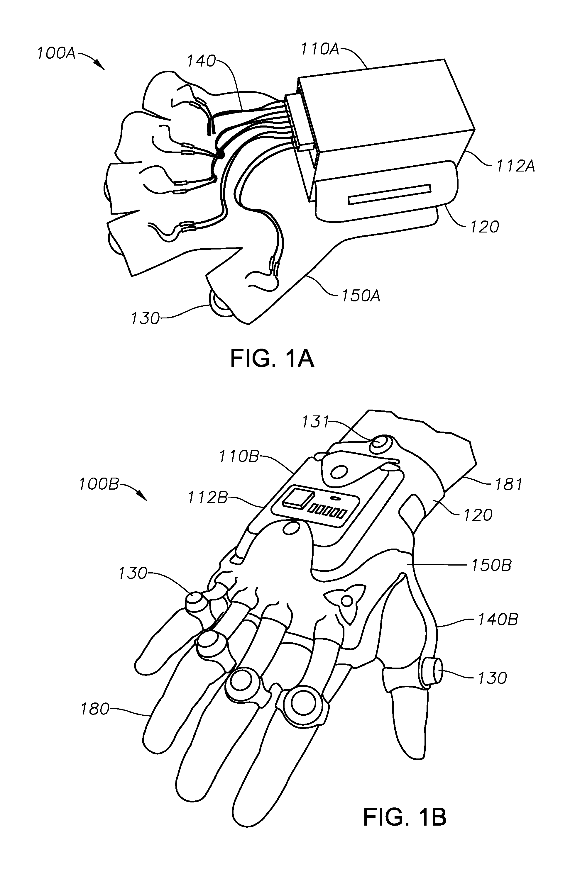
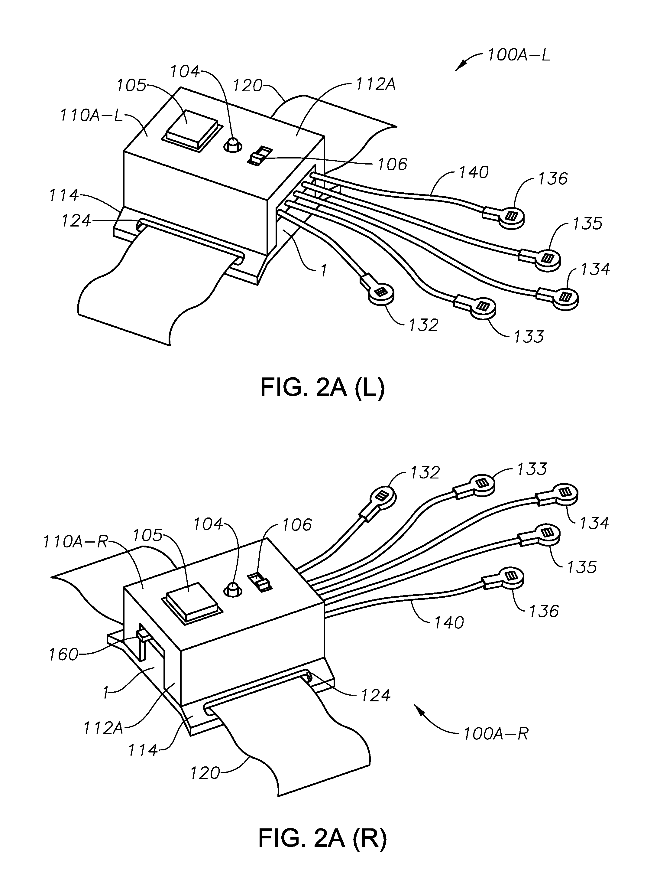
[0039]FIG. 1A is a perspective view of a portable rehabilitation device 100A according to the present invention, in one embodiment. The device 100A shown in the illustrative embodiment of FIG. 1A generally includes a control unit 110A. The control unit 110A defines a micro-processor (seen at 111 in FIG. 3A) and associated circuitry held within a housing 112A. The housing 112A, in turn, is optionally secured to a patient's wrist (not shown) or other extremity using a strap 120 or other securing means.

[0040]In one embodiment the microprocessor is the MSP430F2013 provided by Texas Instruments, Inc. of Plano, Tex. However, any suitable microprocessor may be used that allows a patient to activate and control cycles for somatosensory inputs.

[0041]The rehabilitation device 100A also includes a plurality of micro-motors 130. The micro-motors 130 are transducers that convert electrical energy into mechanical energy. In one aspect, the micro-motors 130 are so-called coin vibration motors, suc...


PUM


Abstract

A therapeutic device for improving voluntary control of paretic muscles in a patient extremity is provided. The therapeutic device is designed to be portable and may be strapped onto a patient's wrist or ankle. The device employs a plurality of micro-motors configured to deliver vibratory sensations to a patient extremity as somatosensory inputs. Each micro-motor is dimensioned to reside on a patient's respective finger or along their foot. The therapeutic device also includes a micro-processor programmed to actuate the micro-motors for designated times and in pre-programmed sequences, and a housing containing the micro-processor. A method of using somatosensory input as a functional guidance to improve motor function in a patient extremity is also provided.

Description

CROSS REFERENCE TO RELATED APPLICATIONS[0001]This application claims the benefit of U.S. Ser. No. 61 / 645,682 filed as a provisional application on May 11, 2012. That application was entitled “Portable Hand Rehabilitation Device,” and is incorporated herein in its entirety by reference.STATEMENT REGARDING FEDERALLY SPONSORED RESEARCH OR DEVELOPMENT[0002]Not applicable.THE NAMES OF THE PARTIES TO A JOINT RESEARCH AGREEMENT[0003]Not applicable.BACKGROUND OF THE INVENTION[0004]1. Field of the Invention[0005]The present invention relates to rehabilitative devices. More specifically, the invention relates to a portable device for enhancing motor function in paretic extremities, such as the hands of a stroke victim.[0006]2. Technology in the Field of the Invention[0007]Many individuals in the United States suffer from limited motor function in their extremities. This may be due to any of several causes. Some individuals may, for example, have suffered a stroke. The term “stroke” is a lay t...

Claims


Application Information

Patent Timeline
Patent Type & Authority Patents(United States)
IPC IPC(8): A61H1/02A61H23/00A63B71/06A63B22/00A63B23/16A63B69/00
CPCA61H1/0285A61H1/0288A61H23/00A63B21/4019A63B22/00A63B23/16A63B71/0622A63B69/0053A63B2022/0092A63B2022/0094A63B2071/0655A63B2207/02A63B2225/20A63B2225/50A63B2225/74
Inventor LIU, YUNELSON, RANDALL J.
Owner UNIV OF TENNESSEE RES FOUND
Why Eureka
Try Eureka