Injector apparatus having a clutch to inhibit forward movement of the plunger

a technology of injector apparatus and plunger, which is applied in the direction of infusion syringes, other medical devices, intravenous devices, etc., can solve the problems of complicated devices, unidirectional movement of the dose setting, and awkward for those with limited dexterity to exer

Active Publication Date: 2016-08-16
OWEN MUMFORD
View PDF242 Cites 22 Cited by
  • Summary
  • Abstract
  • Description
  • Claims
  • Application Information

AI Technical Summary

Benefits of technology

[0011]In an arrangement where the dose setting element is isolated from the force of the drive spring during the dose setting routine, the dose setting element can be rotated easily, and also preferably can be moved in the reverse sense if the user moves the dose setting element past a required dose. Isolating the dose setting element means that the dose-setting movement of said dose setting element is not resisted by said spring.
[0014]The clutch arrangement preferably includes a clutch element moveable between disengaged and engaged positions. Thus the clutch element may be adapted to move axially with said dose setting element, whereby axial movement of said dose setting element from a first, rest, position to a second, dose setting position causes said clutch element to engage to inhibit movement of said plunger. It is also convenient for the dose setting element and the housing to include complementary abutments that engage to prevent relative rotation of said dose setting element relative to said housing when the dose setting element is in its rest position, but which disengage to allow dose setting rotation of the dose setting element when it is in its setting position. In this manner, the dose setting element may be moved axially from its rest position to its dose setting position, then turned to dial in a required dosage volume, and then returned axially to its rest position to lock it against rotation.
[0020]The stop member could simply be an abutment surface provided on the dose setting element. This would allow the maximum useable extent of angular movement of the dose setting element to be just short of 360°. This would mean that the indicia needed to be fairly closely packed in some instances. Accordingly it is preferred for there to be an intermediate dial or shuttle member threadedly engaged with the dose setting element and constrained to rotate with the rotatable one of the plunger and the control member, with the extent of relative angular movement of the dial or shuttle member and the dose setting element being set by the relative position of the stop member associated with the dose setting element. The provision of a threaded dial or shuttle member means that it is now possible to set a dose of several turns. This has advantages both in terms of the available size for the indicia, and also allows greater flexibility over the choice of the pitch of the thread between the plunger and the control member. In a particularly preferred arrangement, the dosage indicia may be provided as a helical strip on one of said complementary dose setting elements, and read off via a marker or window on the other dose setting element.
[0029]In the above arrangement, the injector apparatus may for example be provided with a fully preloaded spring so that the user is not required to input the mechanical energy required to express the doses. This renders the device particularly suitable for those with limited dexterity or poor grip.
[0037]whereby on release of said drive mechanism said control member and said second dose-setting element rotate until the second element returns to said first limit position with respect to the first element, thereby preventing further rotation of the control member.
[0049]the apparatus being configurable between a first position in which the motive force of the drive spring is transmitted via the dose setting element to the housing to be reacted thereby, and a second position in which a clutch element is moved into a position in which motive force of the drive spring is transmitted via the clutch element to the housing to be reacted thereby, so that dose setting movement of the dose setting element is not resisted by the drive spring.

Problems solved by technology

The dose setting movement is unidirectional only due to the ratchet action between the drive sleeve and the drive collar.
This means that it can be awkward for those of limited dexterity to exert sufficient grip to rotate the dose setting knob against the bias of the drive spring.
To allow dose setting reversal in case of setting overshoot, a bi-directional ratchet mechanism is then needed, or otherwise a disconnection mechanism is required, either of which complicate the device.

Method used


Image

  • Injector apparatus having a clutch to inhibit forward movement of the plunger
  • Injector apparatus having a clutch to inhibit forward movement of the plunger
  • Injector apparatus having a clutch to inhibit forward movement of the plunger

Examples


Embodiment Construction

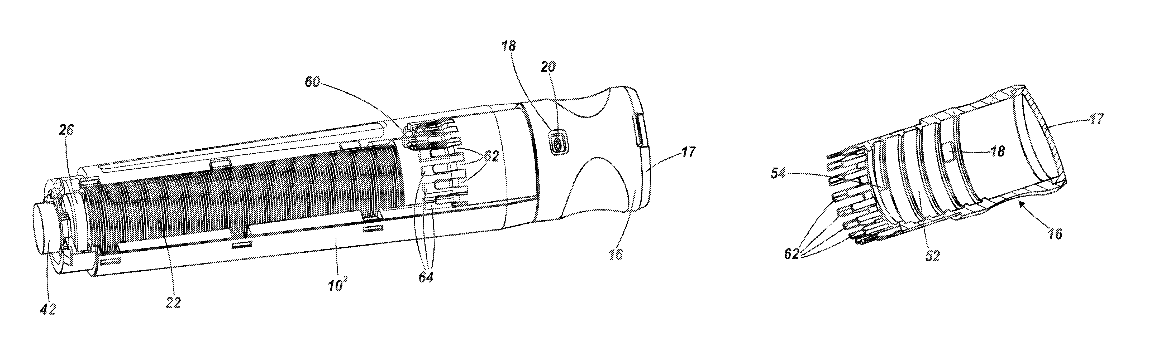
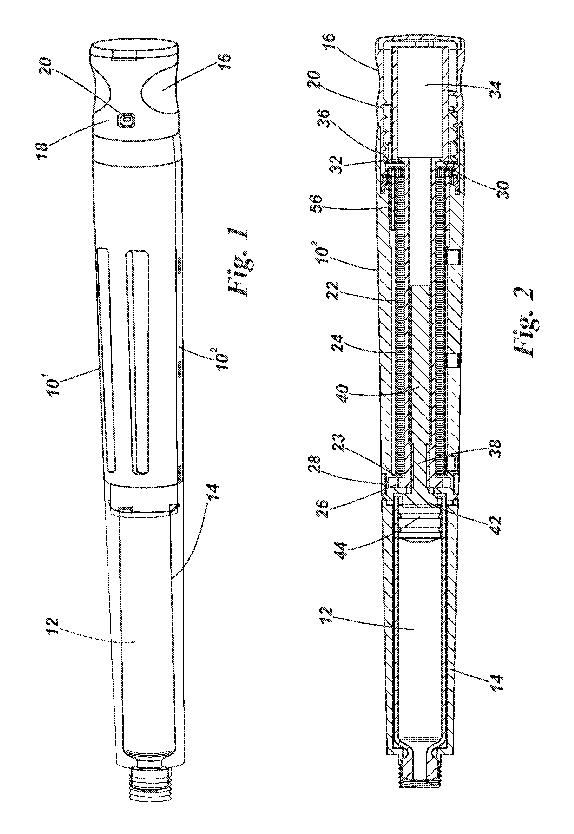
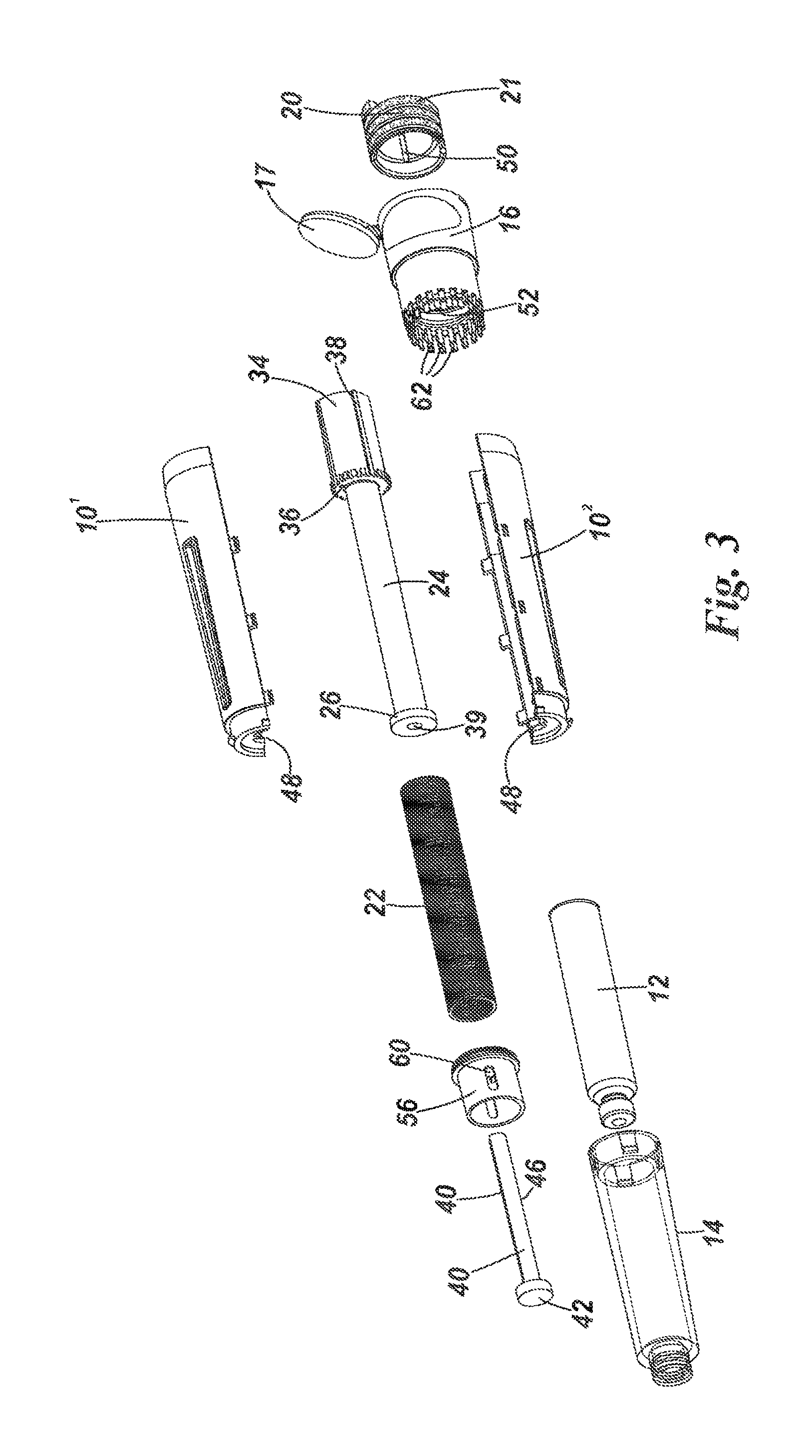
[0061]The embodiment of pen injector illustrated in FIGS. 1 to 6 is designed to be a disposable automatic pen type injector capable of expelling a succession of doses of variable preset magnitude from a cartridge. The injector comprises a body made up of symmetric body halves 101 and 102 which may be snap-fitted or glued together. A cartridge or syringe 12 is received in a transparent forward cartridge housing 14 which is a snap-fit on the forward end of the body halves 101, 102. On the rear end of the body is mounted a dose setting knob 16 having a window 18 through which a dose dial 20 is visible. As to be described below, the device contains a preloaded torsion spring which in this particular embodiment supplies the entire force required to express all the useable dosage volume in the cartridge. Doses are set by pulling the dose setting knob 16 rearwardly, rotating it until the required dosage unit is visible on the dose dial and then pushing the dose dial back in to release the ...


PUM


Abstract

An injector apparatus includes a housing (101, 102) for a cartridge or syringe, a plunger (40) for cooperating in use with the cartridge or syringe to express successive doses, a dose setting arrangement (16, 20) to select a dose volume, and a drive mechanism (22, 24) releasable to advance the plunger in respective predetermined increments of magnitude to express the successive doses. The drive mechanism includes a drive spring (22) for imparting movement directly or indirectly to the plunger (40), and the dose setting arrangement includes a dose setting element (16) moveable in a dose setting routine to define a magnitude of an increment of movement of the plunger for a given dose. The drive mechanism further includes a clutch arrangement (56) operable during the dose setting routine to inhibit forward movement of the plunger and / or to isolate the dose setting element from the force of the drive spring.

Description

[0001]This invention relates to injector apparatus and in particular, but not exclusively, to such apparatus used for injecting multiple doses of variable magnitude, for example of insulin.BACKGROUND OF THE INVENTION[0002]In our earlier Autopen® device, a rotatable dose setting knob attached to the rear end of the pen injector is connected to a hollow drive sleeve that carries an annular ratchet surface at its front end which engages a corresponding ratchet surface on a threaded drive collar. The threaded drive collar is threadedly engaged with the stem of a plunger so that rotary movement of the drive collar is converted into a linear advance of the plunger. A trigger can be moved to release the drive collar for rotary movement. During a dose setting routine, with the drive collar held against rotation by the trigger, a dose is dialled in by rotating the dose setting knob and the drive sleeve against a spring bias provided by a main drive spring. The dose setting movement is unidir...

Claims


Application Information

Patent Timeline
Patent Type & Authority Patents(United States)
IPC IPC(8): A61M5/20A61M5/315A61M5/24A61M5/30A61M5/31
CPCA61M5/20A61M5/24A61M5/3129A61M5/315A61M5/31536A61M5/31548A61M5/31553A61M5/31556A61M5/31558A61M5/31561A61M5/31575A61M2005/2407A61M2005/2492A61M2005/3103A61M2205/581A61M2205/583A61M5/31583A61M5/31585A61M2005/202A61M5/2033A61M5/31551
Inventor COWE, TOBY
Owner OWEN MUMFORD
Why Eureka
Try Eureka