Female terminal assembly

a terminal assembly and female technology, applied in the direction of electrical equipment, coupling device connections, connections effected by permanent deformation, etc., can solve the problem of increasing the force of inserting the terminal, and achieve the effect of reducing the insertion for

Active Publication Date: 2016-12-06
YAZAKI CORP
View PDF21 Cites 10 Cited by
  • Summary
  • Abstract
  • Description
  • Claims
  • Application Information

AI Technical Summary

Benefits of technology

[0028]Therefore, in order to solve the foregoing problems, an object of the invention is to provide a female terminal assembly in which an insertion force can be reduced without providing any low insertion force lever in a connector so that it is possible to contribute to miniaturization of the connector itself and further meet market needs for multipolarization of a terminal.

Problems solved by technology

Therefore, there is a problem that a force for inserting the terminal may increase.
In this manner, a worker's burden can be reduced but provision of the low insertion force lever in the connector becomes an obstacle to meeting market needs for miniaturization of the connector itself or multipolarization of the terminal.

Method used


Image

  • Female terminal assembly
  • Female terminal assembly
  • Female terminal assembly

Examples


first embodiment

Female Terminal Assembly 10 According to First Embodiment of Invention

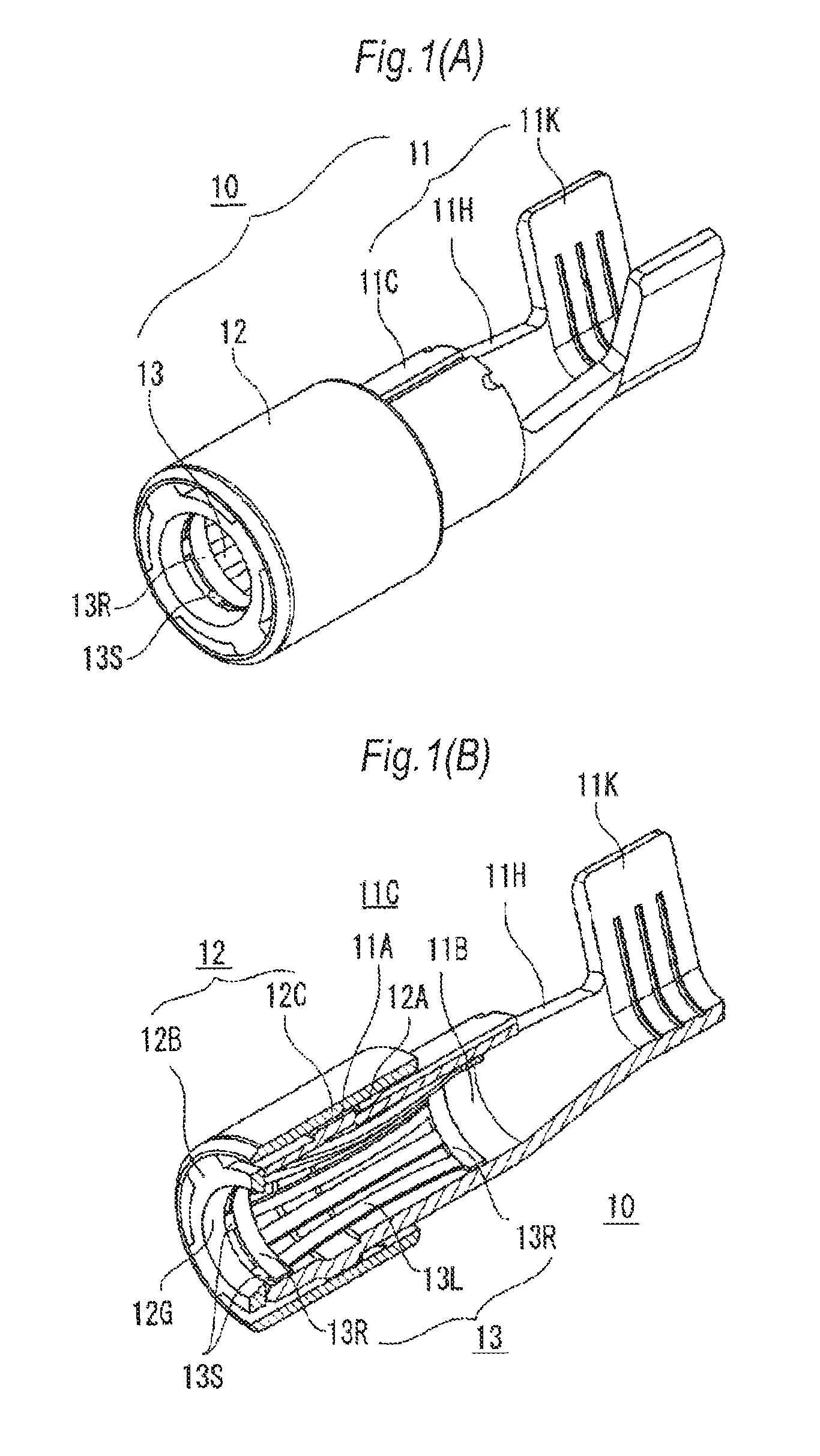
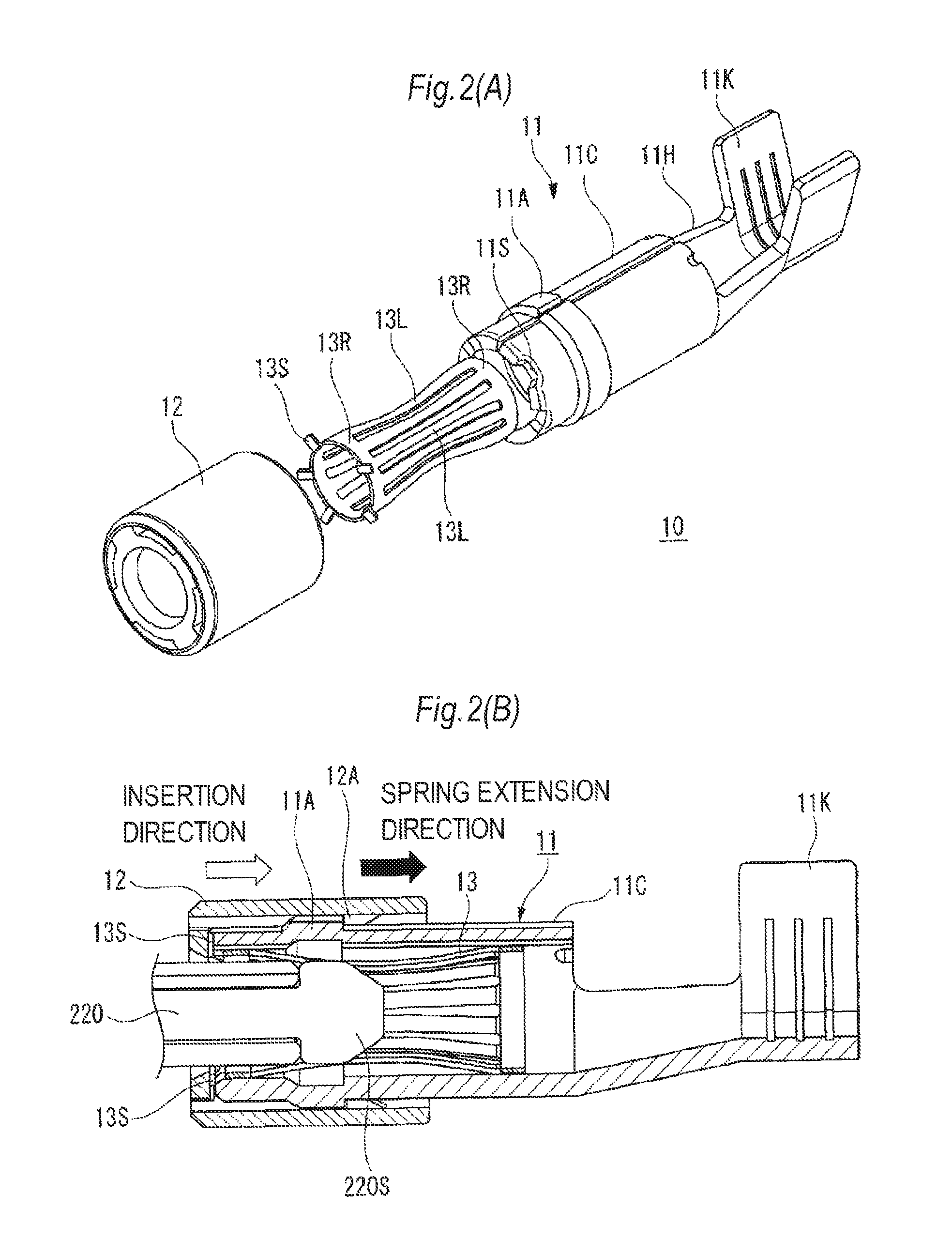
[0054]FIG. 1 and FIG. 2 show a first embodiment of a female terminal assembly according to the invention. FIG. 1(A) is a perspective view of the female terminal assembly according to the first embodiment of the invention. FIG. 1(B) is a longitudinal sectional view along an axial direction of the female terminal assembly in FIG. 1(A). FIG. 2(A) is an exploded perspective view of the female terminal assembly in FIG. 1(A). FIG. 2(B) is a longitudinal sectional view of a spring portion which explains reduction of an insertion force in the female terminal assembly in FIG. 1(A).

[0055]In FIG. 1(A), the female terminal assembly 10 includes a female terminal body 11, a resin cap 12, and a spring contact 13.

[0056]The female terminal body 11 and the spring contact 13 are formed as metal plates punched out respectively. The female terminal body 11 is rounded and formed into a circular cylindrical shape by press working. The r...

second embodiment

Female Terminal Assembly 20 According to Second Embodiment of Invention

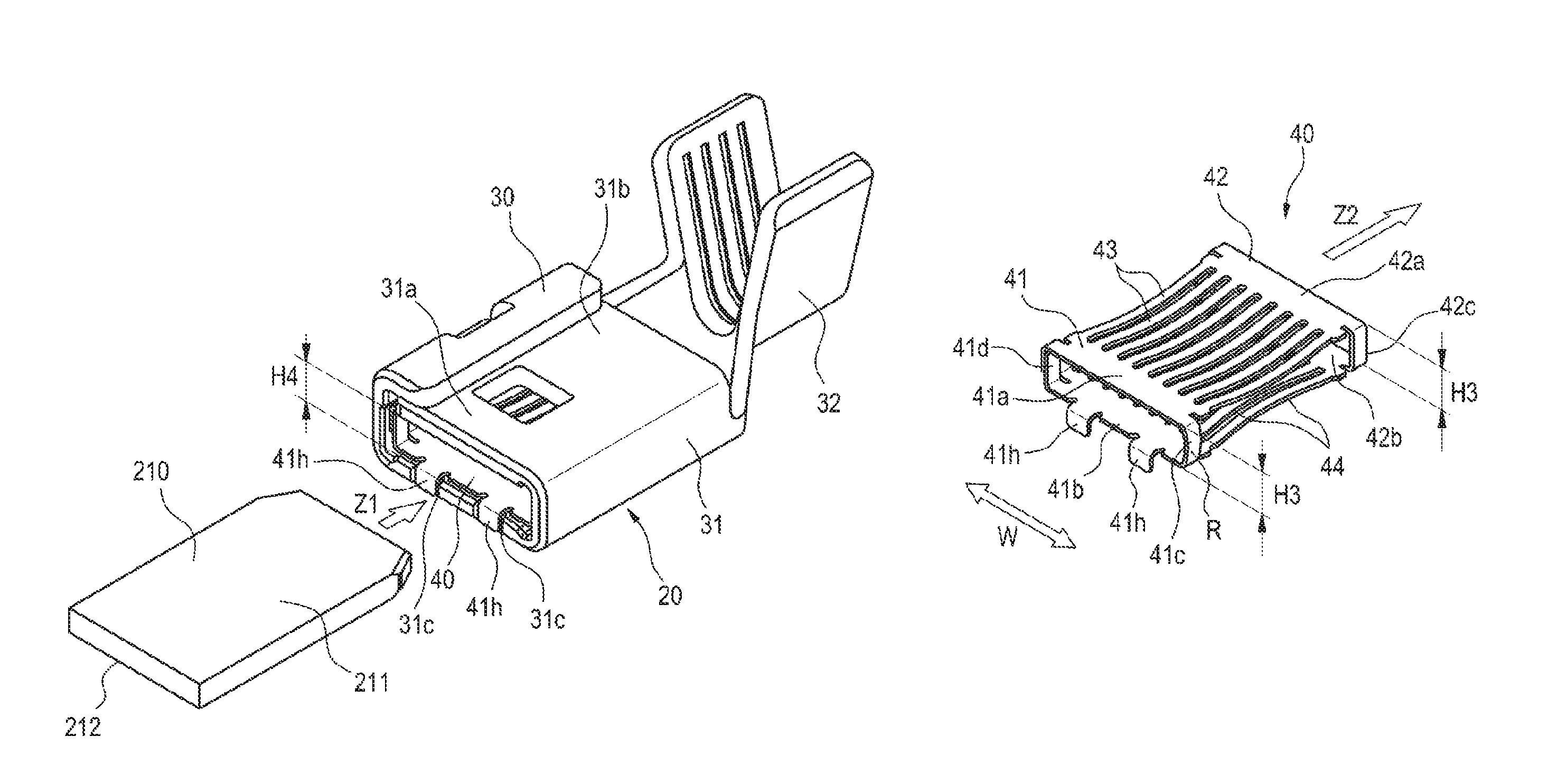
[0079]FIGS. 3 to 8 show a female terminal assembly according to a second embodiment of the invention. FIG. 3(A) is a perspective view of the female terminal assembly according to the second embodiment of the invention. FIG. 3(B) is a perspective view of a spring contact received in a female terminal body in FIG. 3(A). FIG. 4 is a perspective view of the spring contact shown in FIG. 3(B) when seen from another angle. FIG. 5 is a longitudinal sectional view before a male terminal is fitted into the female terminal assembly shown in FIG. 3(A). FIG. 6 is an enlarged view of a portion P in FIG. 5. FIG. 7 is a longitudinal sectional view showing a state in which the male terminal is in the middle of being fitted into the female terminal assembly shown in FIG. 3(A). FIG. 8 is a longitudinal sectional view showing a state in which fitting of the male terminal into the female terminal assembly shown in FIG. 3(A) is comple...


PUM


Abstract

A female terminal assembly includes: a female terminal body in which a male terminal receiving space is formed internally; and a cylindrical spring contact which is received in the male terminal receiving space from a male terminal insertion side of the female terminal body. A lock portion formed at a male terminal insertion-side end portion of the spring contact is fixed to a male terminal insertion-side end portion of the female terminal body.

Description

CROSS REFERENCE TO RELATED APPLICATIONS[0001]This application is a continuation of PCT application No. PCT / JP2014 / 067274, which was filed on Jun. 27, 2014 based on Japanese Patent Application (No. 2013-141883) filed on Jul. 5, 2013 and Japanese Patent Application (No. 2013-210435) filed on Oct. 7, 2013, the contents of which are incorporated herein by reference.BACKGROUND OF THE INVENTION[0002]1. Field of the Invention[0003]The present invention relates to a female terminal assembly of a connector housing used for connection etc. between a battery of an electric car and various equipments. Particularly, it relates to a female terminal assembly for large current, in which a cylindrical spring contact making contact with a mating male terminal is provided inside a terminal body.[0004]2. Description of the Related Art[0005]A female terminal assembly described in Japanese Patent No. 3498832 is provided as one of female terminal assemblies for large current according to the background ar...

Claims


Application Information

Patent Timeline
Patent Type & Authority Patents(United States)
IPC IPC(8): H01R13/187H01R4/18H01R13/506H01R4/48
CPCH01R13/187H01R4/184H01R13/506H01R4/4881
Inventor HIRAKAWA, TAKAYOSHIKUBOSHIMA, HIDEHIKOYOSHIOKA, TOSHIKAZUYAMADA, YUYA
Owner YAZAKI CORP
Why Eureka
Try Eureka