Radiation analyzer including a support for tilting an energy-dispersive radiation detector
a radiation detector and radiation analyzer technology, applied in the direction of liquid/fluent solid measurement, machines/engines, instruments, etc., can solve the problems of difficult detection of x-rays, deterioration of x-ray detection accuracy, and interruption of x-rays, etc., to achieve efficient radiation detection
- Summary
- Abstract
- Description
- Claims
- Application Information
AI Technical Summary
Benefits of technology
Problems solved by technology
Method used
Image

Examples
first embodiment
1. First Embodiment
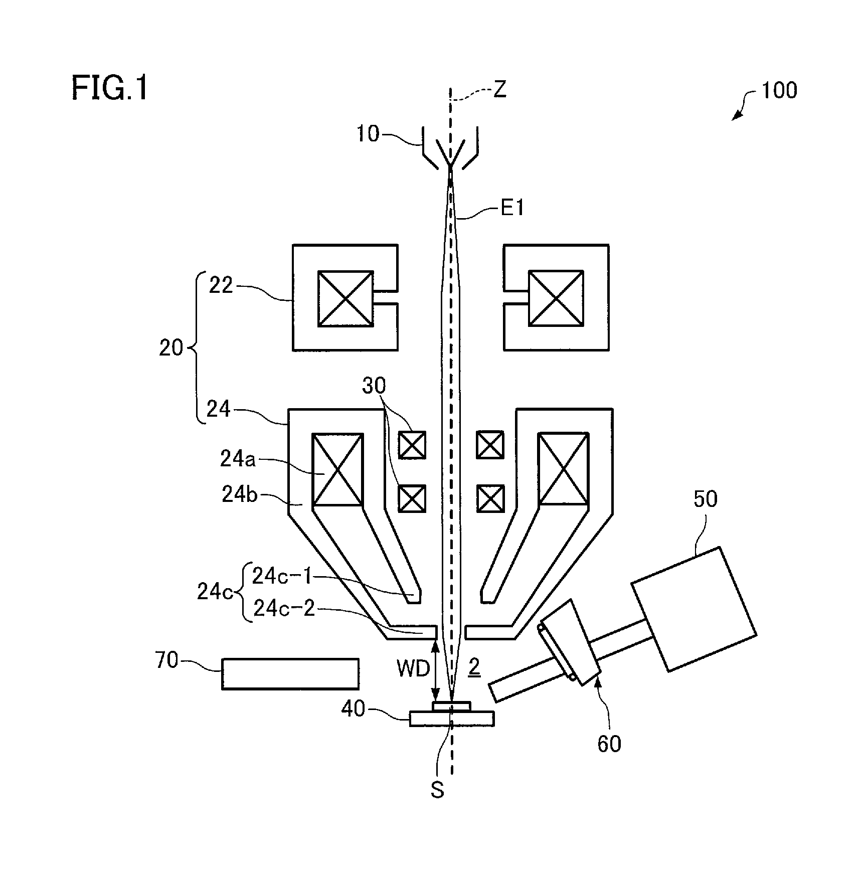
[0054]A radiation analyzer according to a first embodiment of the invention is described below with reference to the drawings. FIG. 1 schematically illustrates the radiation analyzer (radiation analyzer 100) according to the first embodiment. The first embodiment illustrates an example in which the radiation analyzer 100 is a scanning electron microscope (SEM).
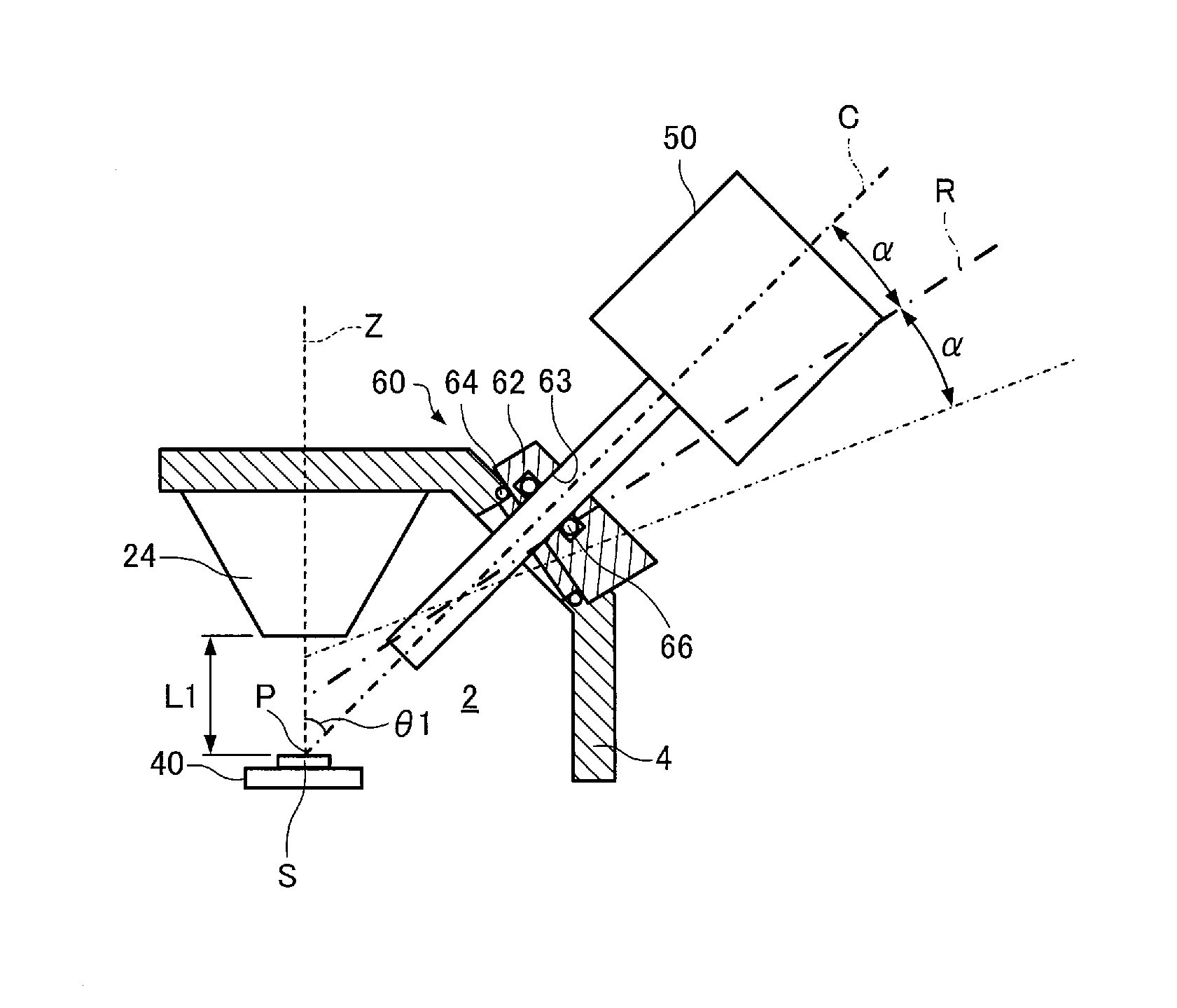
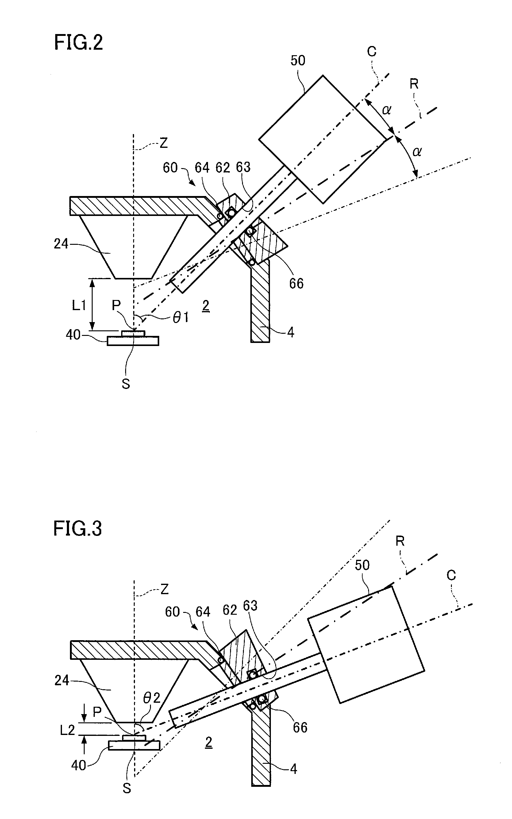
[0055]As illustrated in FIG. 1, the radiation analyzer 100 includes an electron beam source (primary ray source) 10, an optical system 20, a scanning deflector 30, a sample stage 40, a radiation detector 50, a support 60, and a secondary electron detector 70. Note that a wall 4 (see FIGS. 2 and 3) (that divides a sample chamber 2 in which a sample S is disposed) is omitted in FIG. 1.
[0056]The radiation analyzer 100 is configured so that electron beams E1 generated by the electron beam source 10 are focused by the optical system 20 and used as an electron probe, and secondary electrons released from the elect...
second embodiment
2. Second Embodiment
[0090]A radiation analyzer according to a second embodiment of the invention is described below with reference to FIGS. 4 and 5. FIGS. 4 and 5 schematically illustrate a support 60 that is included in a radiation analyzer 200 according to the second embodiment. Note that FIG. 4 illustrates a state in which a radiation detector 50 is set to a first state, and FIG. 5 illustrates a state in which the radiation detector 50 is set to a second state.
[0091]The following description focuses on the differences between the radiation analyzer 200 according to the second embodiment and the radiation analyzer 100 according to the first embodiment, and detailed description of the same features is omitted.
[0092]As illustrated in FIGS. 4 and 5, the radiation analyzer 200 is configured so that the support 60 includes a rotation section 210 that supports the radiation detector 50 so as to be rotatable around the rotation axis R, and a drive section 220 that drives the rotation sec...
third embodiment
3. Third Embodiment
[0100]A radiation analyzer according to a third embodiment of the invention is described below with reference to FIG. 6. FIG. 6 schematically illustrates a support 60 that is included in a radiation analyzer 300 according to the third embodiment. The following description focuses on the differences between the radiation analyzer 300 according to the third embodiment and the radiation analyzer 100 according to the first embodiment, and detailed description of the same features is omitted.
[0101]As illustrated in FIG. 6, the radiation analyzer 300 is configured so that the support 60 includes a swing section 310 that supports the radiation detector 50 so as to be swingable, and a drive section 320 that drives the swing section 310.
[0102]The support 60 further includes an arm 322, a spring 324, a first securing section 330, and a second securing section 332.
[0103]The support 60 is mounted on the wall 4 through the first securing section 330 (interface). The gap betwee...
PUM
 Abstract
Description
Claims
Application Information
 - R&D
- Intellectual Property
- Life Sciences
- Materials
- Tech Scout
- Unparalleled Data Quality
- Higher Quality Content
- 60% Fewer Hallucinations
Browse by: Latest US Patents, China's latest patents, Technical Efficacy Thesaurus, Application Domain, Technology Topic, Popular Technical Reports.
© 2025 PatSnap. All rights reserved.Legal|Privacy policy|Modern Slavery Act Transparency Statement|Sitemap|About US| Contact US: help@patsnap.com