System of autonomous vehicles

Active Publication Date: 2017-01-10
LELY PATENT
View PDF21 Cites 0 Cited by
  • Summary
  • Abstract
  • Description
  • Claims
  • Application Information

AI Technical Summary

Benefits of technology

[0005]One object of the present invention is to provide a system and method of the type mentioned in the introduction, wherein collisions

Problems solved by technology

However, solutions of this type require a substantial amount of communication traffic, with a risk of faults therein and consequently still a risk of co

Method used


Image

  • System of autonomous vehicles
  • System of autonomous vehicles
  • System of autonomous vehicles

Examples


Embodiment Construction

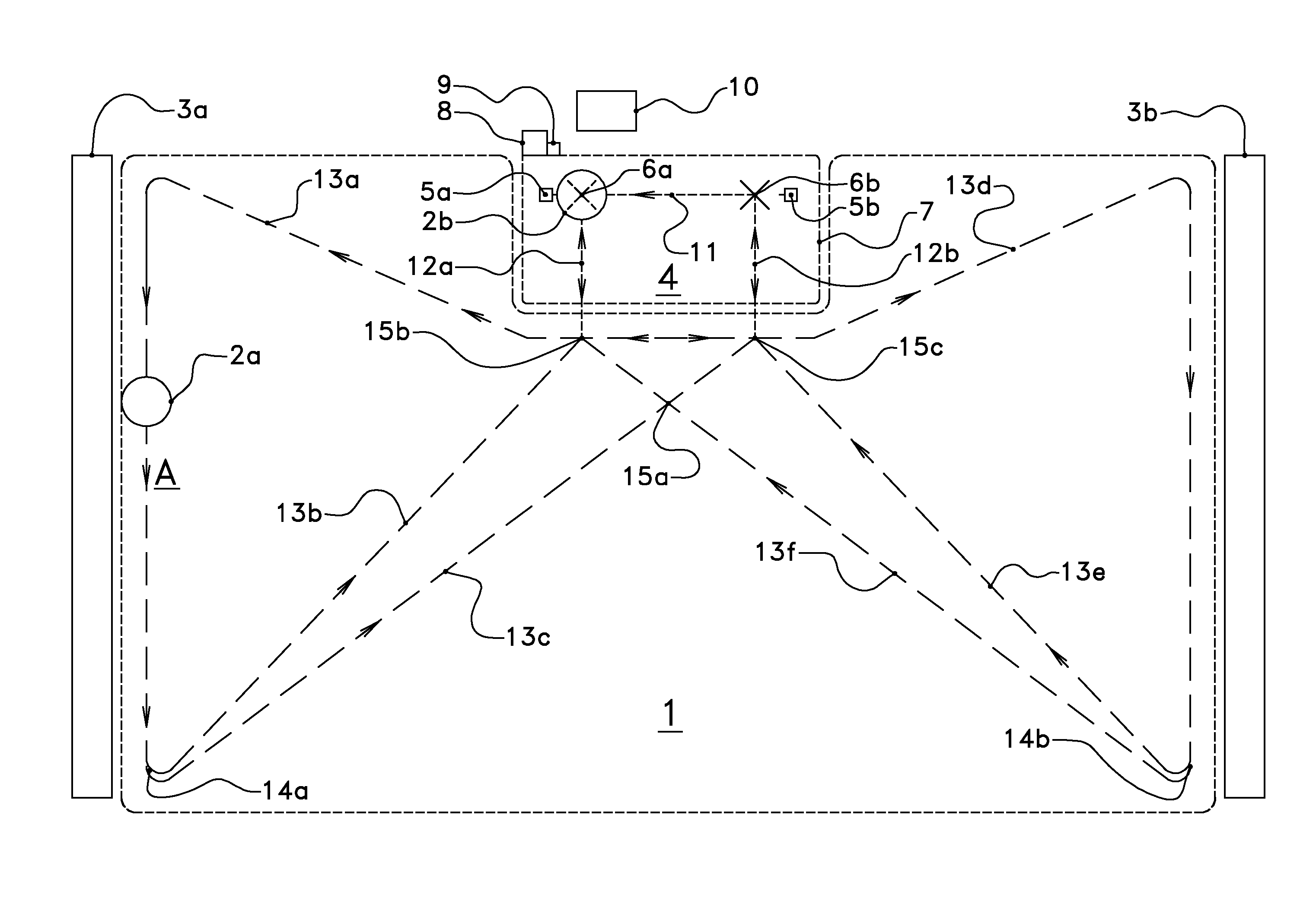
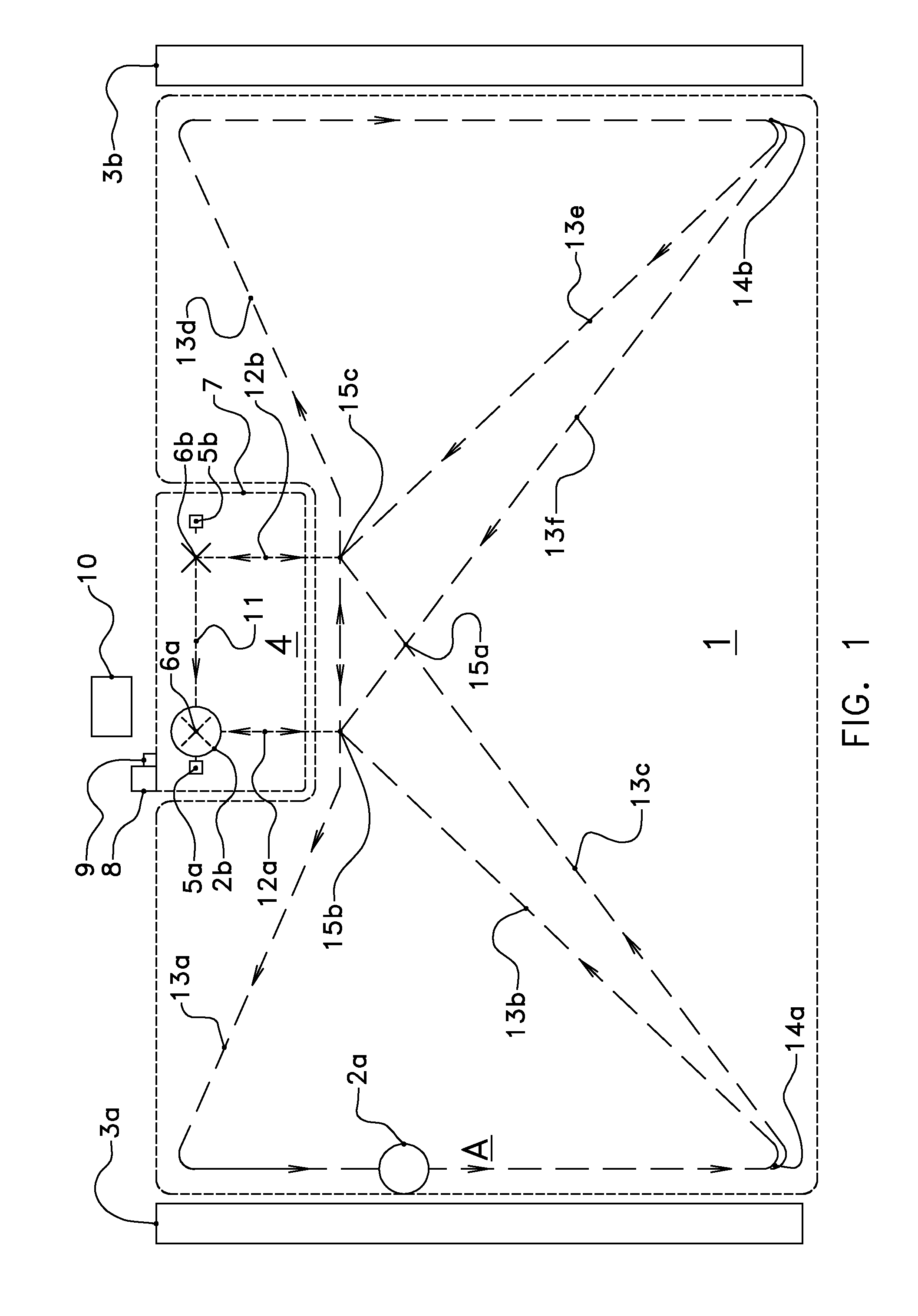
[0029]FIG. 1 shows a schematic top view of a system according to the invention. Herein, 1 indicates an operational area in which a first and a second vehicle 2a, 2b are located. 3a and 3b are two feedways.

[0030]4 denotes a charging area in which two charging pillars 5a and 5b are located and which charging area is defined by the boundary 7. 8 denotes a control device, and 9 an ID device, and 10 denotes a feed-loading device. Furthermore, two charging positions 6a and 6b are indicated, between which an advancing route 11 is indicated. 12a and 12b denote two route start and end stages, which adjoin consecutive route stages 13a-13f.

[0031]14a and 14b denote two decision positions and 15a, 15b and 15c denote three intersection points.

[0032]In the system shown, the vehicle 2a moves in the arrow direction A along the feedway 3a. Here, the vehicle 2a comes along route stage 13a and will continue its path up to the decision point 14a. Either route stage 13b or route stage 13c will be chosen...


PUM


Abstract

A system and method for control of the system, with a plurality of autonomous vehicles having intersecting routes, a control, an operational area, and a predefined place with positions provided with a vehicle presence detection device. The method includes detecting the presence of the vehicles in a detection device, and beginning to travel with a first vehicle according to a travel action. The travel action is chosen from travelling of a route through the operational area from a predefined place, and an advancing action within a predefined place from a first detection device to a second detection device which is not yet occupied. Beginning to travel is carried out only if each of the vehicles has been detected as present at one of the predefined places, or, at most one vehicle has the status “not present at one of the predefined places” if the travel action relates to an advancing action.

Description

BACKGROUND OF THE INVENTION[0001]Field of the Invention[0002]The invention relates to a system and a method for controlling such a system, of N unmanned autonomous vehicles, where N≧2, a control device for at least partially controlling at least one of the autonomous vehicles, an operational area with a floor over which the vehicles can move, wherein the vehicles are each configured to travel independently over one or more routes which are possible for that vehicle, wherein for at least one vehicle at least one of the possible routes intersects at least at one point with at least one possible route of another of the vehicles, and at least one predefined place which adjoins the operational area, with in total M predefined positions which are each provided with at least one detection device to detect the presence of one of the vehicles and to signal the presence to the control device, where M≧2. A system of this type with a plurality of autonomous vehicles is known per se.[0003]Descri...

Claims


Application Information

Patent Timeline
IPC IPC(8): G05D1/02G08G1/00
CPCG05D1/0289G05D1/0291G08G1/20A01K1/0128A01K1/105A01K5/0266
Inventor VAN KUILENBURG, JAN MARTINUSVAN DEN BERG, KAREL
Owner LELY PATENT
Why Eureka
Try Eureka