

Card edge connector
- Summary
- Abstract
- Description
- Claims
- Application Information
AI Technical Summary
Benefits of technology
Problems solved by technology
Method used
Image

Examples
first embodiment
[0029]An implementation of a card edge connector according to the invention is described by way of specific embodiments. Other advantages and effects of the invention may be understood apparently by those skilled in the art from contents disclosed in the specification. The invention may also be implemented or applied by way of other different embodiments. Various modifications and changes to various details in the specification may be based on different perspectives and applications without departing from scope of the invention. Further, the drawings of the invention are for describing technical contents only, and are not drawn in actual scales. The concept of the invention is detailed further in an implementation below, while scope of the invention is not limited to any concept.
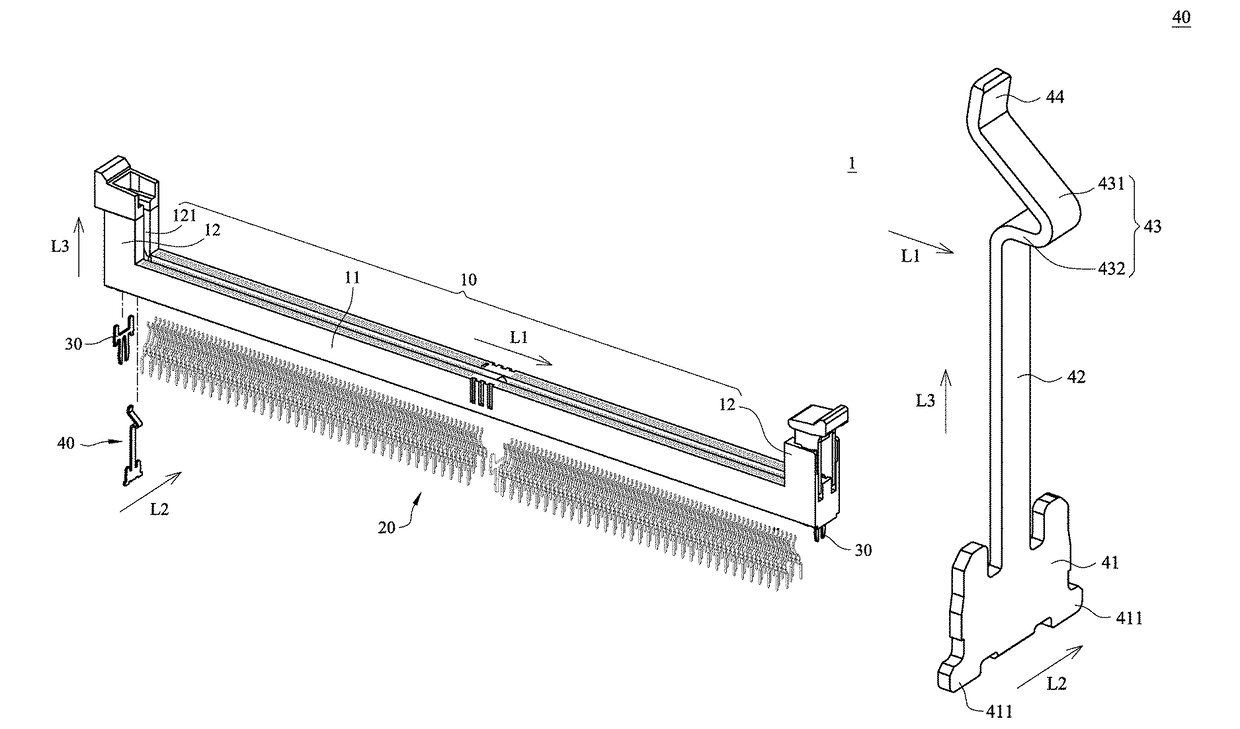
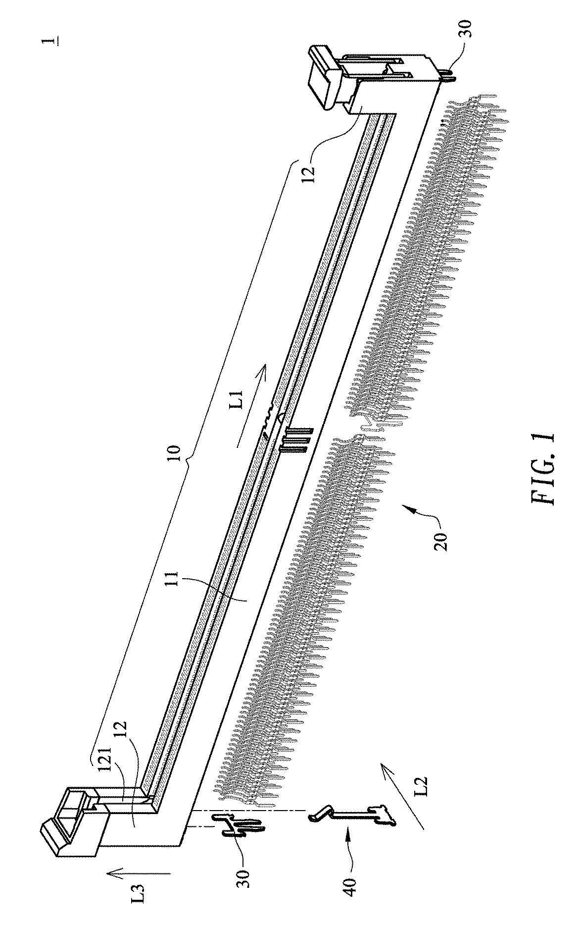
[0030]Refer to FIG. 1, which is an exploded schematic diagram showing a card edge connector according to the invention. As shown in the figure, the card edge connector 1 comprises a base housing 10, several ...
second embodiment
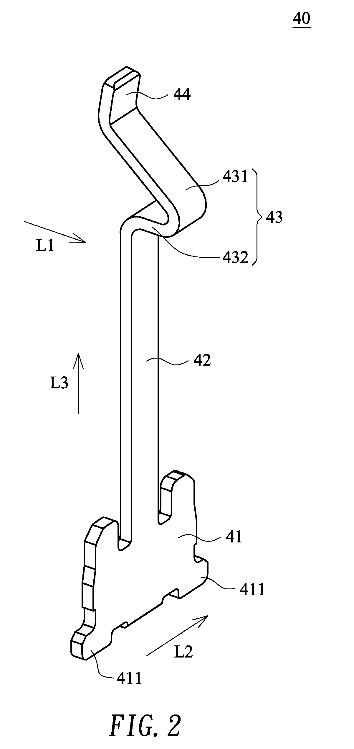
[0037]Refer to both FIGS. 7 and 8, which are a stereo exploded schematic diagram showing a second embodiment of a card edge connector and a stereo schematic diagram showing an elastic clamping part according to the invention, respectively. As shown in the figures, the card edge connector 1′ comprises a base housing 10, several connection terminals 20, two plate fasteners 30 and an elastic clamping part 40′. The embodiment differs from the aforementioned embodiment in that the structure of the elastic clamping part 40′ has a different aspect in comparison to the aforementioned embodiment, and has a structure shown in FIG. 8. Connection relations of other components in this embodiment are the same as what mentioned in the aforementioned embodiment, and the description is as above, so that only the elastic clamping part 40′ of this embodiment will be described in detail below.
[0038]Refer to both FIGS. 8 and 9. The elastic clamping part 40′ is fastened in one of the clamping portions 12...
PUM
 Abstract
Description
Claims
Application Information