
Laser processing apparatus, processed data generating method, and computer program
A technology of laser processing and processing data, applied in laser welding equipment, metal processing equipment, computer control, etc., can solve the problem of not obtaining the processing angle, etc., and achieve high-precision results
Patent Information
- Authority / Receiving Office
- CN · China
- Patent Type
- Applications(China)
- Current Assignee / Owner
- Publication Date
- 2009-04-01
- Estimated Expiration
- Not applicable · inactive patent
Smart Images
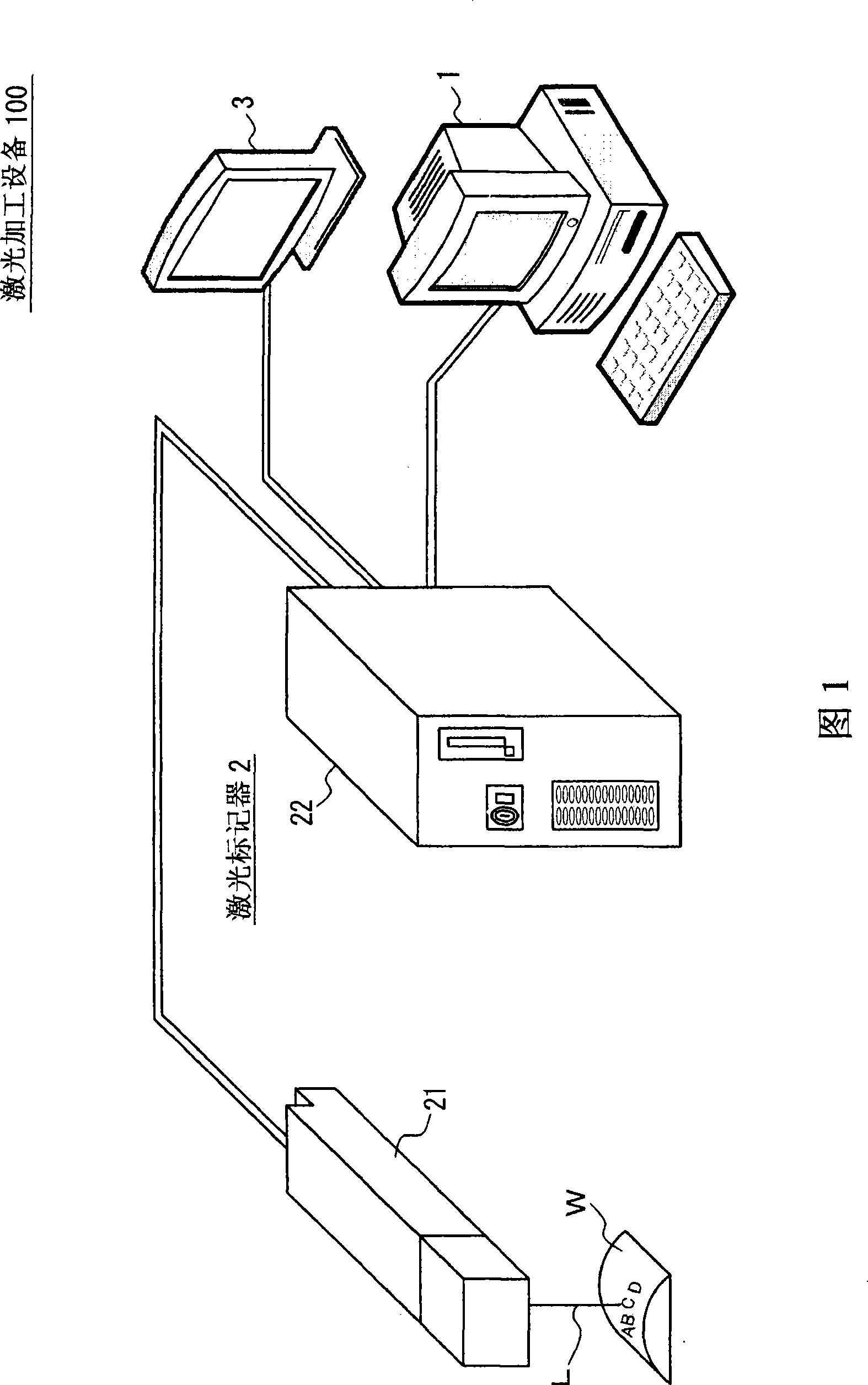
Figure 1 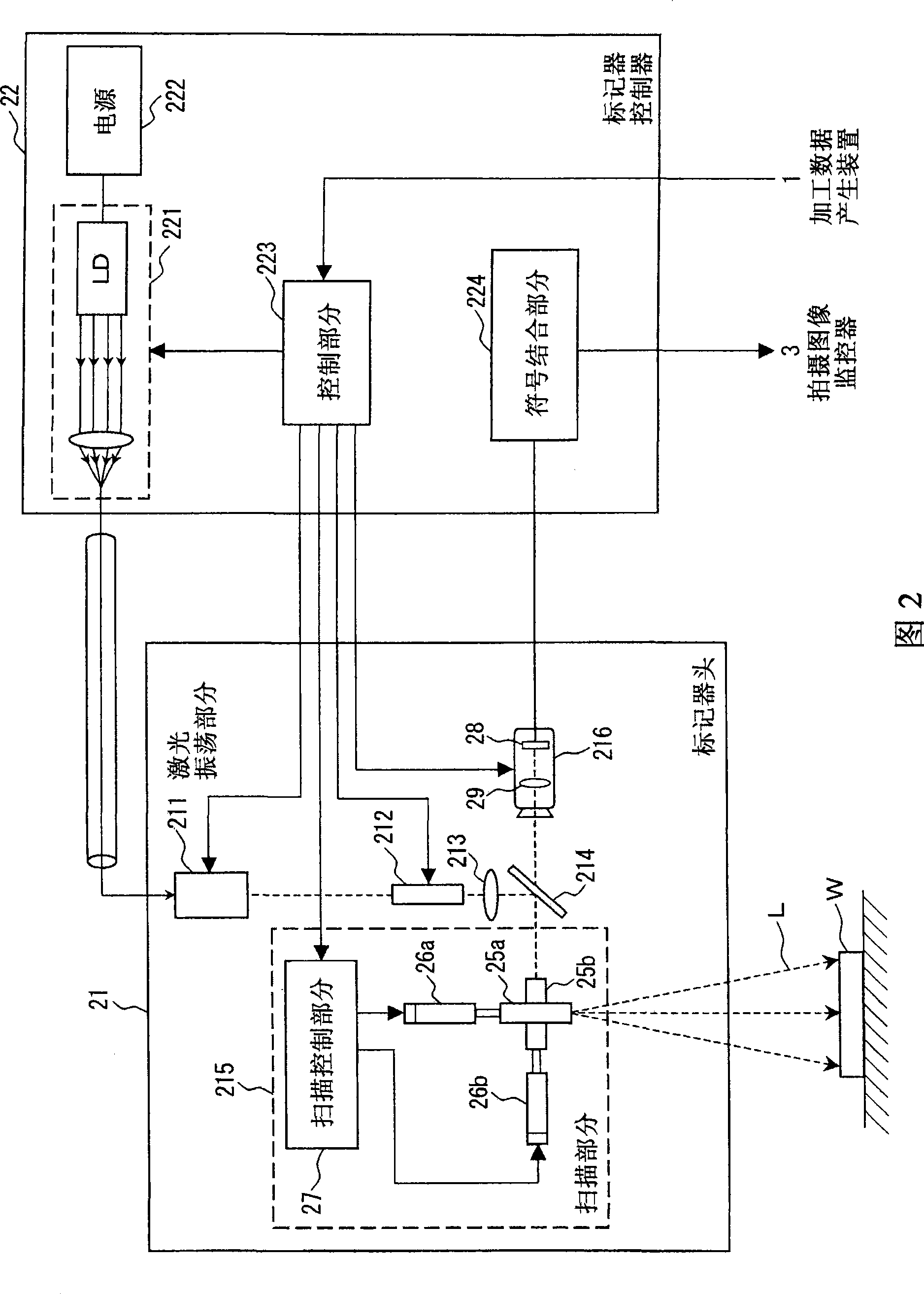
Figure 2 
Figure 3
Abstract
Description
technical field
[0001] The present invention relates to a kind of laser processing equipment, a kind of processing data generating method and a kind of computer program, in particular, the present invention relates to a kind of when the laser processing equipment produces the processing data used for controlling the laser processing to make the user An improved method of specifying the processing position on the above. Background technique
[0002] FIG. 20 is a view showing a schematic structure of a conventional laser processing apparatus 101 . A processing data generating device 1 for generating processing data according to user operations and a laser marker 2 for irradiating a workpiece W with a laser beam L constitute a laser processing apparatus 101 . The laser marker 2 is further composed of a marker head 21 for scanning the laser beam L on the workpiece W as an article to be processed and a marker for performing operation control on the marker head 21 based on proces...
Examples
no. 1 example
[0060] FIG. 1 is a view showing an example of a schematic configuration of a laser processing apparatus 100 according to a first embodiment of the present invention. Composed of a processing data generating device 1 for generating processing data, a laser marker 2 for irradiating a workpiece W with a laser beam L, and a captured image monitor 3 for displaying a captured image of the workpiece W captured by the laser marker 2 The laser processing apparatus 100 is constituted. The laser marker 2 is further composed of a marker head 21 for scanning the laser beam L, and a marker controller 22 for performing operation control of the marker head 21 based on machining data from the machining data generating device 1 .
[0061] In a conventional laser processing apparatus, processing data is generated while checking whether a processing pattern is formed on a specific portion of the workpiece W desired by a user by observing the workpiece W. On the other hand, in the laser processin...
no. 2 example
[0121] In the first embodiment, an example has been described in which the coordinate system defining the installation plane of the processing data generating device 1 coincides with the coordinate system defining the scanning area of the laser marker 2 . In this embodiment, a case will be described in which the coordinate system of the installation plane of the processing data generating device 1 is different from the coordinate system of the scanning area of the laser marker 2, and the coordinate system transformation process includes rotation and mirror image.
[0122] FIG. 12 is an explanatory diagram showing an example of a coordinate system for setting a plane and a scanning area, in which Figure 12A shows the coordinate system of the scanned area, Figure 12B The coordinate system of the setting plane displayed on the setting screen 10 is shown in . The setting plane and the scanning area are represented by orthogonal coordinates in which an X axis corresponding t...