
Angle pressure device on outer rotor winding machine
A winding machine and outer rotor technology, applied in the direction of electromechanical devices, manufacturing motor generators, electrical components, etc., can solve problems such as loose coils, uneven lead wires, and uneven angles of broken lines, so as to improve performance and improve performance. quality, effect of avoiding dents or wear
Patent Information
- Authority / Receiving Office
- CN · China
- Current Assignee / Owner
- Publication Date
- 2012-09-19
- Estimated Expiration
- Not applicable · inactive patent
Smart Images
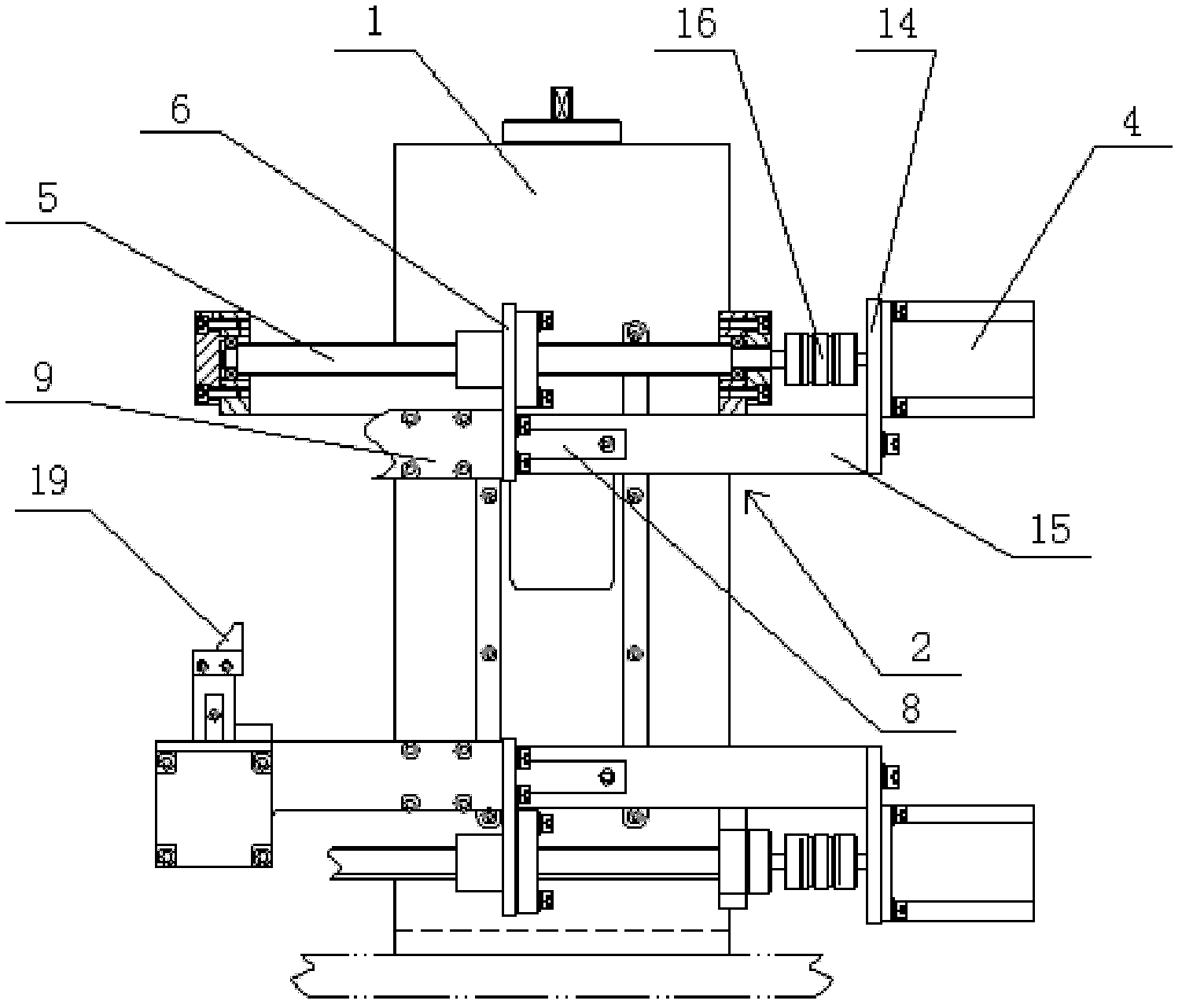
Figure 1 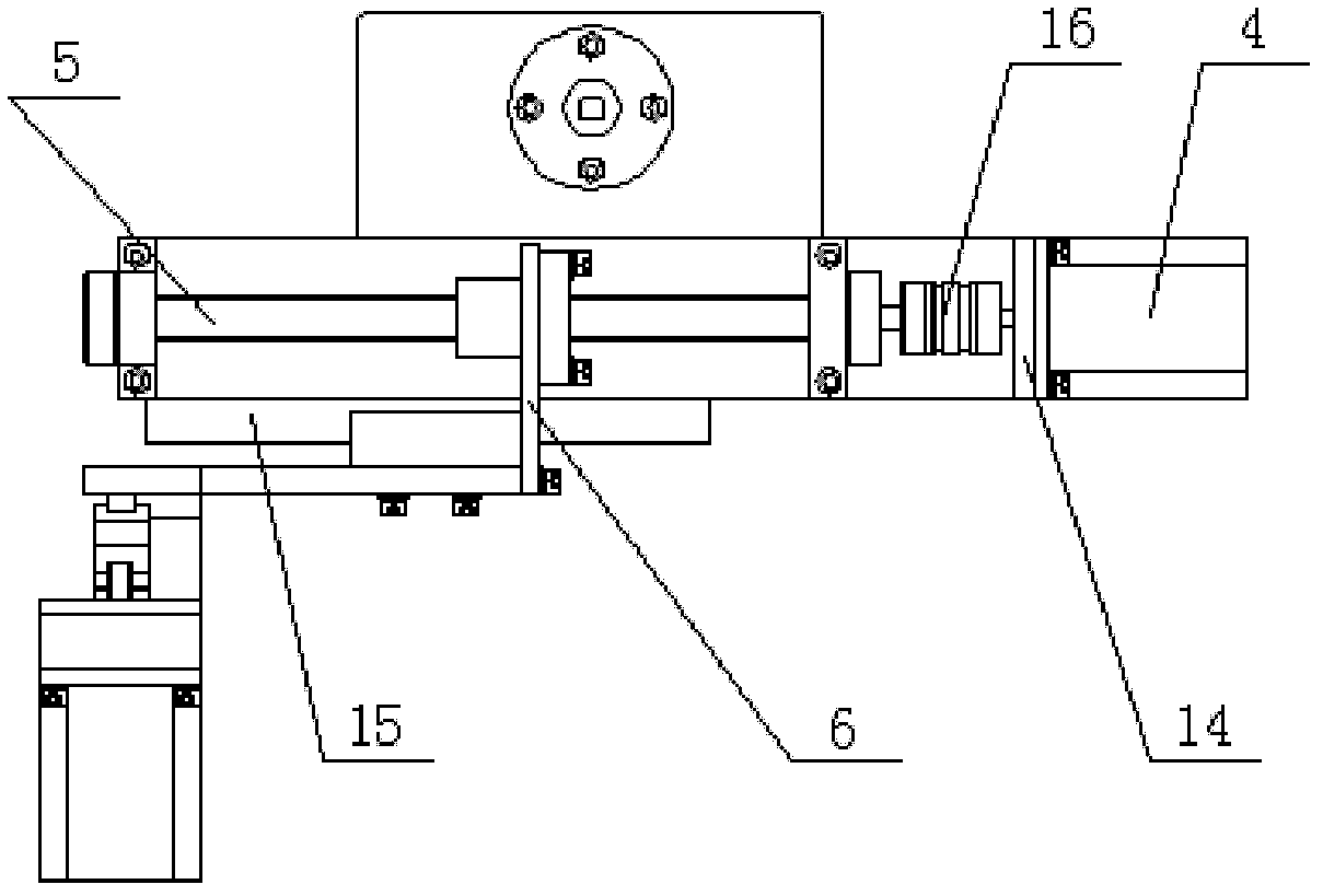
Figure 2 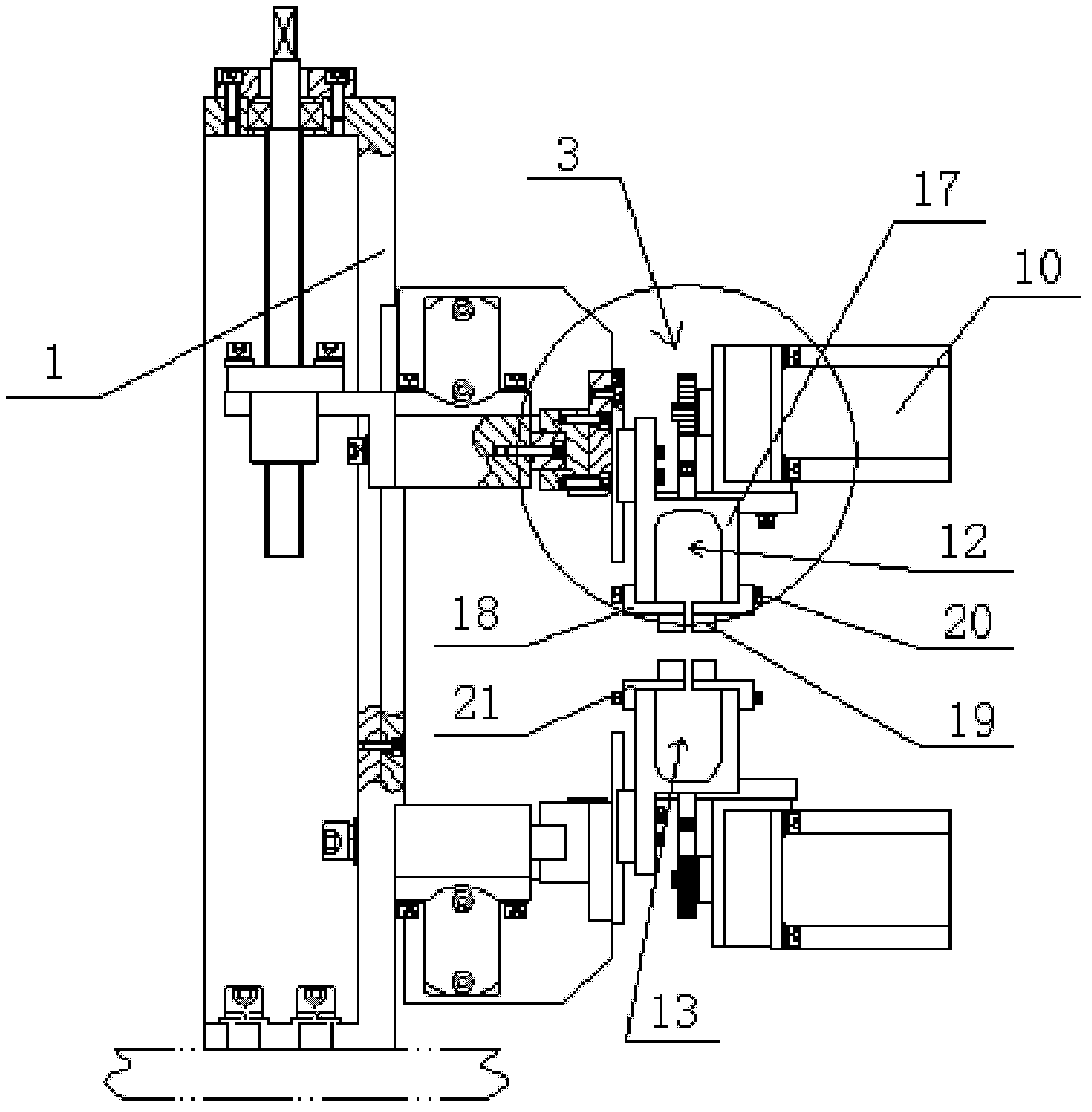
Figure 3
Abstract
Description
technical field
[0001] The invention relates to a winding machine for an induction coil, in particular to a pressure angle device on an outer rotor winding machine. Background technique
[0002] When producing the motor rotor, there is a process of winding the enameled wire into the groove of the rotor. At present, the rotor with fewer grooves in the production line is produced by an ordinary motor rotor winding machine. However, there are more grooves in the production line. When the rotor is used, such as the outer rotor of the battery car (the rotating part (rotor) of the motor is the outer shell of the motor, and the shaft end of the motor is fixed, it is used to fix the motor.), due to the small gap in the line groove, so , the existing ordinary motor stator winding machine can not meet the production requirements, and must also be produced by manual winding, the production efficiency is low, generally a stator takes 15 to 20 minutes, and the product consistency is poor...
Examples
Embodiment 1
[0019] Embodiment one: see Figure 1~4 As shown, an angle-pressing device on an outer rotor winding machine includes a pair of angle-pressing mechanisms arranged up and down oppositely, which are respectively installed on the main box body 1 of the winding machine. The motion pair 2, the lifting linear motion pair 3 and the pressure angle structure installed on the lifting linear motion pair 3, the forward linear motion pair 2 includes a forward motor 4, a forward ball screw 5 connected with the forward motor 4 , the forward screw connection block 6 screwed on the forward ball screw 5, and the forward guide rail 8 arranged perpendicular to the rotor indexing rotation axis of the winding machine, the forward screw connection block 6 is slidably connected to the forward On the guide rail 8; the lifting linear motion pair 3 is connected with the advance screw connecting block 6 through a guide rail connecting plate 9, and the lifting linear motion pair 3 includes a lifting step...