
An annular plunger small displacement rod type oil well pump
An annular column, small displacement technology, applied in the field of oil well pump, annular plunger small displacement rod type oil well pump, can solve the problems of difficult to reduce the theoretical displacement of oil well pump, low pump efficiency, blockage, etc., to reduce the oil lift pipe work , reduce workload, avoid the effect of stuck pump
Patent Information
- Authority / Receiving Office
- CN · China
- Patent Type
- Patents(China)
- Current Assignee / Owner
- Publication Date
- 2015-11-11
- Estimated Expiration
- Not applicable · inactive patent
Smart Images
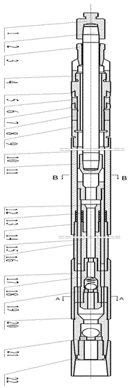
Figure 1 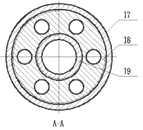
Figure 2 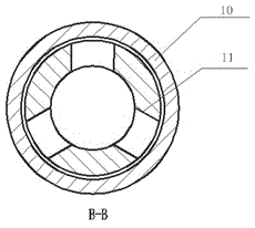
Figure 3
Abstract
Description
technical field
[0001] The invention belongs to the technical field of petroleum exploitation and relates to an oil well pump, in particular to an annular plunger small displacement rod type oil well pump. Background technique
[0002] With the development of the world's oil and gas industry, the proportion of easily developed conventional oil and gas resources in the total remaining oil and gas resources is getting smaller and smaller. Therefore, in the past, ultra-low permeability oilfields with poor reservoir properties, low single-well production and difficult development have become the main battlefield for oil and gas development in my country. In such oilfields, due to the low liquid supply capacity of the formation and the impact of sand production in the formation, it is easy to cause low efficiency of the conventional oil pumping system and serious mud and sand stuck in the pump. The main problems are as follows: 1) The minimum theoretical displacement of the conv...
Examples
Embodiment Construction
[0019] The structural principle and working principle of the present invention will be further described in detail below in conjunction with the accompanying drawings.
[0020] see figure 1 , 2, a small displacement rod oil well pump with annular plunger, comprising an outer pump barrel 16, an inner pump barrel 15, and an annular plunger 14, and an annular plunger 14 is fitted between the outer pump barrel 16 and the inner pump barrel 15, The upper end of the outer pump barrel 16 is connected with an extension collar 10, and the upper end of the extension collar 10 is connected with a support cup assembly, and the support cup assembly is sequentially provided with a support cup reducing joint 9, a support cup pressure cap from bottom to top. 8. The lower supporting cup 7, the supporting cup seat ring 6, the upper supporting cup 5 and the supporting cup mandrel 4, the upper end of the supporting cup assembly is connected with the valve stem guide sleeve 3,
[0021] The lower e...