
Covnenient plug type 3D printing spray head
A 3D printing, plug-in technology, applied in the field of 3D printing nozzles, can solve the problems of circuit connection components occupying a large space, expansion tube blockage, easy damage, etc., to save socket space, good lubricity, and low heat. Effect
Patent Information
- Authority / Receiving Office
- CN · China
- Patent Type
- Applications(China)
- Current Assignee / Owner
- Publication Date
- 2014-09-03
- Estimated Expiration
- Not applicable · inactive patent
Smart Images
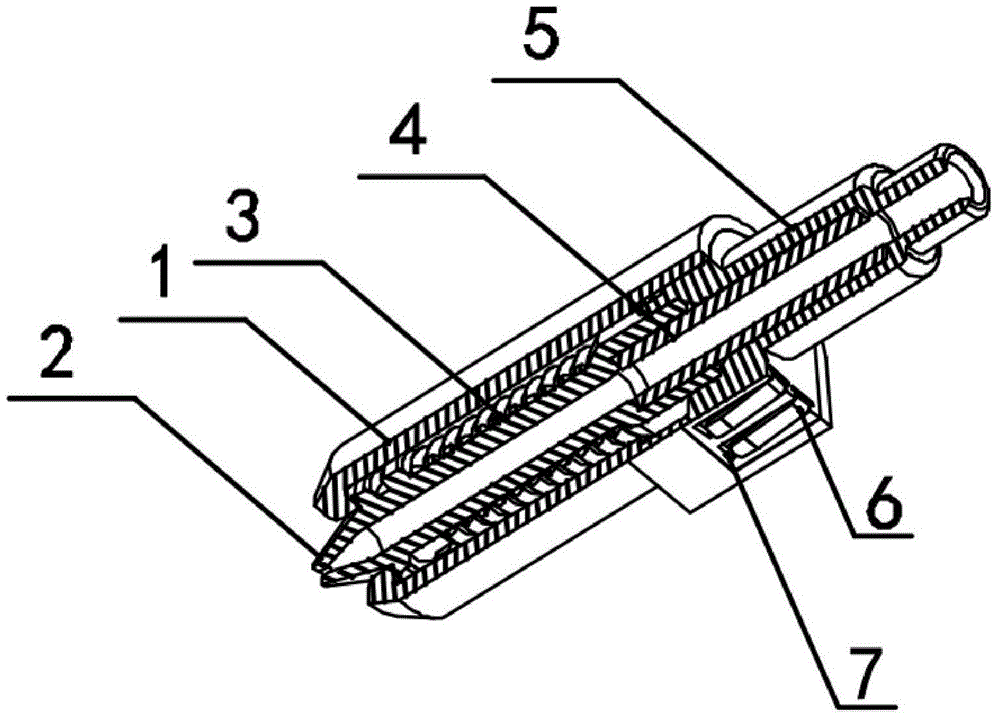
Figure 1 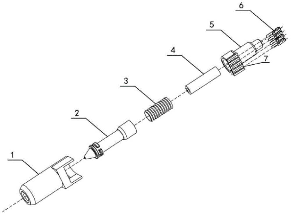
Figure 2
Abstract
Description
technical field
[0001] The invention relates to a 3D printing component, in particular to a 3D printing nozzle. Background technique
[0002] In the past, 3D printing nozzles were integrated on 3D printers and drawing pens and could not be replaced, which limited the scope of use of 3D printing equipment. During the three-dimensional creation process of existing 3D printers and drawing pens, consumables of various colors and materials may be used according to the printing model set by the user. , the nozzles of 3D printers and drawing pens need to be replaced frequently to meet different requirements.
[0003] Improvements have been made to address this problem in the industry. On the one hand, the detachable connection between the 3D printing nozzle and the printing equipment is realized in the mechanical structure. Separation is currently achieved by setting a pin-type power connector on the nozzle holder to connect with the control circuit on the 3D printing device, thu...
Examples
Embodiment 1
[0014] Embodiment 1: the structural representation of the present invention is as figure 1 As shown, it includes a housing 1 , a nozzle 2 , a heating device 3 surrounding the outer wall of the nozzle 2 , a plastic introduction pipe 4 , a fixing seat 5 and a metal terminal 6 .
[0015] The assembly diagram of the present invention is as follows figure 2 As shown, the fixing seat 5 is provided with a through hole and is fixedly arranged in the cavity of the housing 1, the plastic introduction tube 4 is sleeved in the through hole of the fixing seat 5, and is connected with the through hole of the nozzle 2 to form a consumable The conveying cavity; the fixed seat 5 is provided with a terminal card slot 7, and the metal terminal 6 is fixedly arranged on the terminal card slot 7; the power line of the heating device 3 is connected to the metal terminal 6, and the metal terminal 6. SMD connection with the control circuit of the 3D printing device. In this embodiment, it is directl...
Embodiment 2
[0017] Embodiment 2: the structural representation of the present invention is as figure 1 As shown, it includes a housing 1, a nozzle 2, a heating device 3 surrounding the outer wall of the nozzle 2, a plastic introduction pipe 4, a fixing seat 5 and a metal terminal 6, and a temperature sensor is also provided in the cavity of the housing 3.
[0018] The assembly diagram of the present invention is as follows figure 2 As shown, the fixing seat 5 is provided with a through hole and is fixedly arranged in the cavity of the housing 1, the plastic introduction tube 4 is sleeved in the through hole of the fixing seat 5, and is connected with the through hole of the nozzle 2 to form a consumable Conveying cavity; the fixed seat 5 is provided with a terminal card slot 7, and the metal terminal 6 is fixedly arranged on the terminal card slot 7; the power line of the heating device 3 and the signal line of the temperature sensor are connected to the metal terminal 6 Above, the meta...