
Pressing plate type floating clamp
A technology of floating fixtures and pressure plates, which is applied in clamping, manufacturing tools, workpiece clamping devices, etc., can solve problems such as poor clamping effect of workpieces, substandard workpiece quality, and reduced production efficiency, and increase the rate of workpiece quality compliance , processing stability, and the effect of improving production efficiency
Patent Information
- Authority / Receiving Office
- CN · China
- Current Assignee / Owner
- Publication Date
- 2016-02-24
- Estimated Expiration
- Not applicable · inactive patent
Smart Images
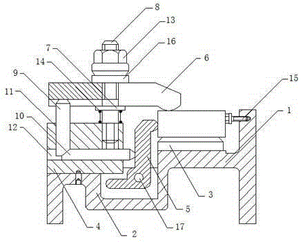
Figure 1
Abstract
Description
technical field
[0001] The invention relates to the field of clamps, in particular to a pressing plate type floating clamp. Background technique
[0002] In a broad sense, any process in the process, the device used to install the workpiece quickly, conveniently and safely, can be called a fixture. Such as welding fixtures, inspection fixtures, assembly fixtures, machine tool fixtures, etc. Among them, machine tool fixtures are the most common, often referred to as fixtures. When processing a workpiece on a machine tool, in order to make the surface of the workpiece meet the technical requirements such as the size, geometric shape, and position accuracy with other surfaces specified in the drawing, the workpiece must be installed and clamped firmly before processing. Fixtures are usually composed of positioning elements, clamping devices, tool setting guide elements, indexing devices, connecting elements, and clamp bodies.
[0003] Jigs and fixture arrangements are well k...
Examples
Embodiment Construction
[0012] The present invention will be described in further detail below by means of specific embodiments:
[0013] The reference signs in the drawings of the description include: upper base 1, lower base 2, protrusion 3, positioning block 4, clamping arm 5, pressure plate 6, support plate 7, bolt 8, first ejector rod 9, second Two push rods 10, first hole 11, second hole 12, nut 13, stage clip 14, screw 15, washer 16, bearing pin 17.
[0014] The embodiment is basically as attached figure 1 Shown: Platen type floating fixture, including a fixing mechanism and a clamping mechanism, the fixing mechanism includes a stepped base, a protrusion 3 for clamping the workpiece and a screw 15 for clamping the workpiece, the base includes an upper base 1 and the lower base 2, the protrusion 3 is arranged on the upper base 1, the screw 15 is arranged on the side wall of the upper base 1; the clamping mechanism is arranged on the lower base 2, and the clamping mechanism includes a positioni...