
Integrated embedded pipe hot stamping die for automobile parts
A technology for hot stamping dies and auto parts, which is applied in the field of sheet metal stamping and forming. It can solve the problems of high precision assembly of inserts, complex mold cooling water system, and long processing cycle, so as to reduce the frequency of cooling water leakage defects and reduce production. Cost and use threshold, manufacturing process cycle and cost reduction effect
Patent Information
- Authority / Receiving Office
- CN · China
- Current Assignee / Owner
- Publication Date
- 2011-04-27
- Estimated Expiration
- Not applicable · inactive patent
Smart Images
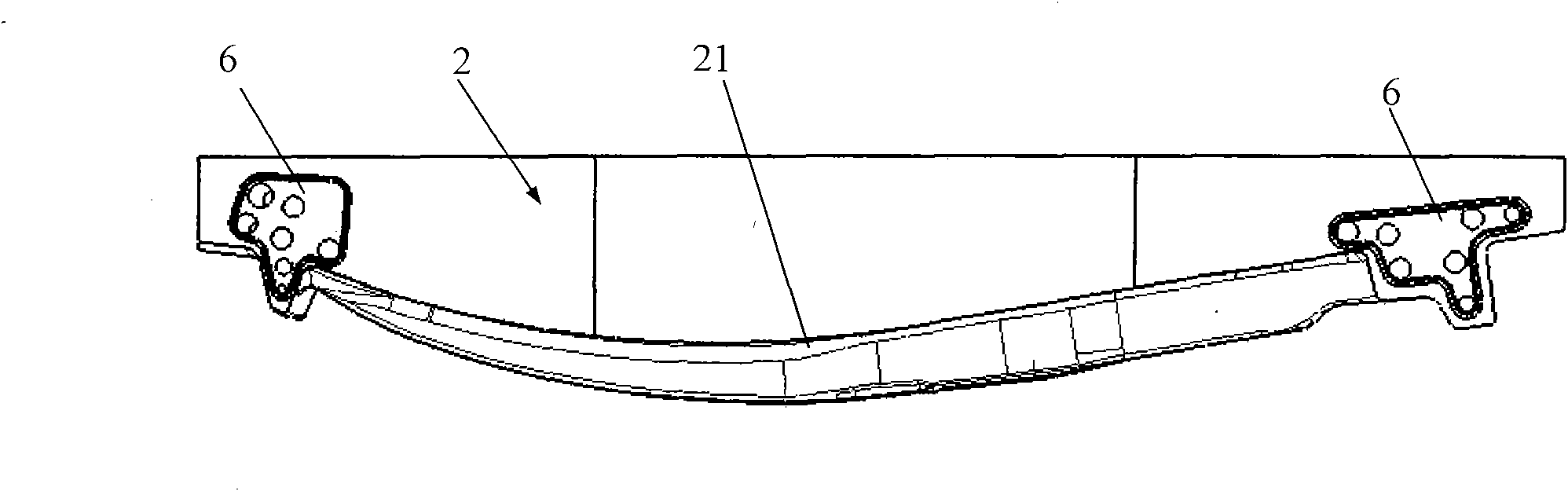
Figure 1 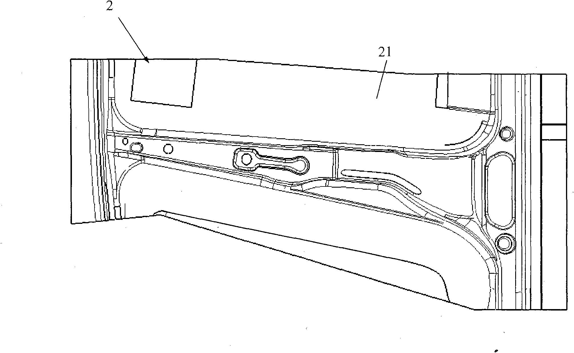
Figure 2 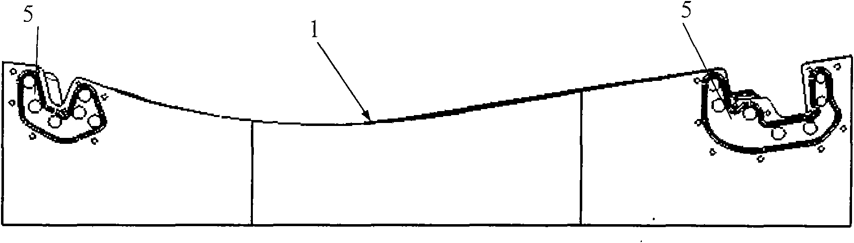
Figure 3
Abstract
Description
technical field
[0001] The invention belongs to the field of stamping and forming of sheet materials, and in particular relates to a hot stamping mold of an integral pre-embedded pipe for automobile parts. Background technique
[0002] Hot stamping is a new forming technology developed in the past 20 years. Its technological feature is to heat the Boron steel plate with an original strength of about 400-600Mpa to the austenitic temperature range, quickly move to the mold and press it quickly, and keep it in the press. In the pressed state, the parts are rapidly cooled through the mold to achieve quenching and strengthening, and a martensitic structure and a tensile strength of about 1500Mpa or even higher are obtained. The use of hot stamping parts in the body structure can greatly improve the collision safety of the body, reduce the weight of the body in white, and meet the requirements of the automotive industry for safety, energy saving, environmental protection, and comf...
Examples
Embodiment Construction
[0031] see Figure 1 to Figure 12 , the auto parts integral pre-embedded tube hot stamping die of the present invention, taking the automobile B-pillar parts as an example, the mold comprises a mold die 1 and a punch 2, which respectively have the same structural shape as the automobile B-pillar parts. The corresponding profiles 11 and 21 are T-shaped at both ends; the cooling water pipelines 3 and 4 are arranged in the profiles of the die die 1 and punch 2, and the cooling water pipelines 3 and 4 are connected by the diversion communication grooves 5 and 6. Seal plugs 7, 8 to form two sets of connected cooling water passages with different flow directions; both die die 1 and punch 2 are externally connected with a water inlet joint 12, 22 and a water outlet joint 13, 23, and are connected with the diversion communication groove 5 , 6 are connected; the cooling water pipelines 3 and 4 are bent and arranged with 6-8 branch pipelines 31 and 41 along the direction of the mold sur...