
Intelligent detection system and method for current temperature signal
An intelligent detection and temperature signal technology, which is applied in non-electrical signal transmission systems, signal transmission systems, thermometers, etc., can solve the problems of high power consumption, poor safety, and clutter interference of current and temperature signal detection devices, so as to prevent damage and Threat to personal safety, convenient installation, and the effect of reducing system power consumption
Patent Information
- Authority / Receiving Office
- CN · China
- Current Assignee / Owner
- Publication Date
- 2017-02-01
Smart Images
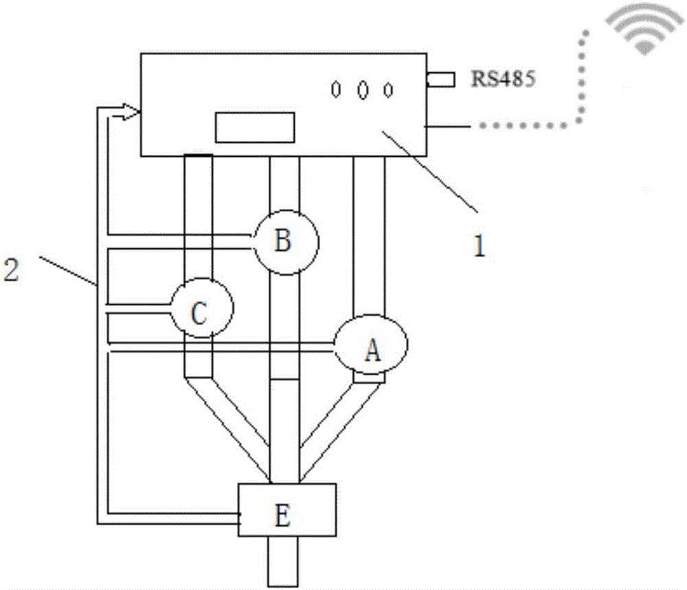
Figure 1 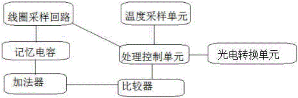
Figure 2 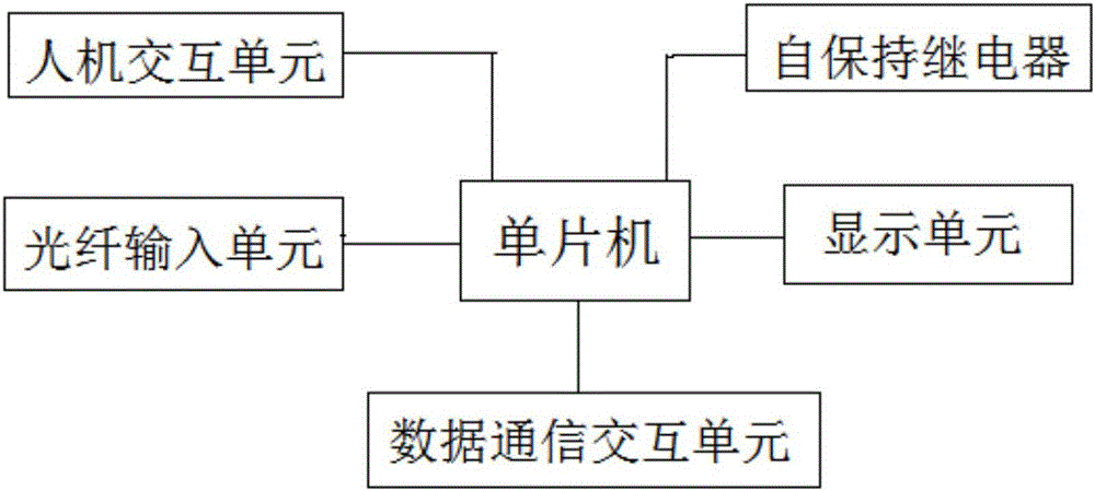
Figure 3
Abstract
Description
technical field
[0001] The invention relates to the technical field of electric power automation, in particular to an intelligent detection system and method for current and temperature signals. Background technique
[0002] At present, when the current is detected during cable transmission, the commonly used products include cable type current temperature sensor and segment code LCD display fault indicator and other products. In the existing cable-type current temperature detection and fault indication device, the signal captured by the sensor is transmitted to the host through the cable, and the current and temperature information of the cable after the host receives the signal.
[0003] However, the conventional current and temperature signal detection device has the following defects: First, the conventional cable-type product sensor needs an external power supply to work normally due to the large power consumption of the cable transmission, and the cable transmission pr...
Examples
Embodiment Construction
[0030] The specific implementation manners of the present invention will be further described in detail below in conjunction with the accompanying drawings and examples. The following examples are used to illustrate the present invention, but are not intended to limit the scope of the present invention.
[0031] In describing the present invention, it should be understood that the terms "center", "longitudinal", "transverse", "upper", "lower", "front", "rear", "left", "right", " The orientations or positional relationships indicated by "vertical", "horizontal", "top", "bottom", "inner", "outer", etc. are based on the orientation or positional relationships shown in the drawings, and are only for the convenience of describing the present invention and simplifying Describes, but does not indicate or imply that the device or element referred to must have a specific orientation, be constructed in a specific orientation, and operate in a specific orientation, and therefore should n...