
Improved method and structure for extra-high water head planar slide gate
A sliding gate and ultra-high water head technology, applied in hydraulic engineering, marine engineering, coastline protection, etc., can solve problems such as difficulty in closing the gate, gate vibration, and gate top offset, etc., to enhance mechanical performance, reduce vibration, water flow, etc. Smooth flow effect
Patent Information
- Authority / Receiving Office
- CN · China
- Current Assignee / Owner
- Publication Date
- 2017-03-22
Smart Images
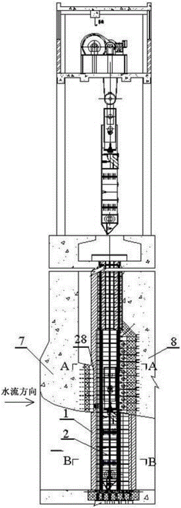
Figure 1 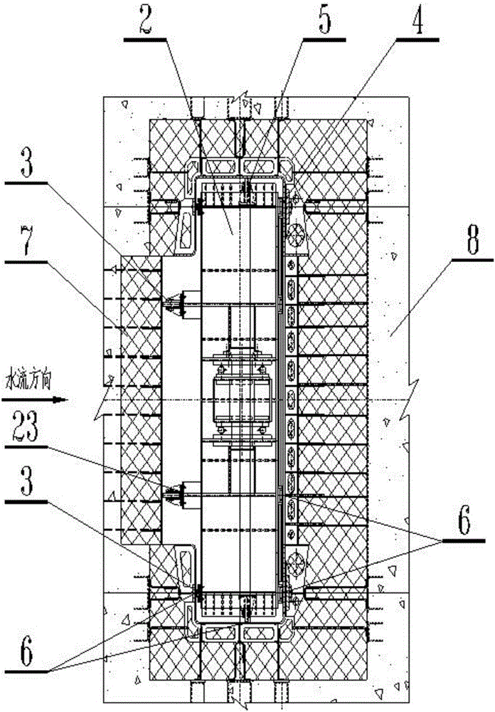
Figure 2 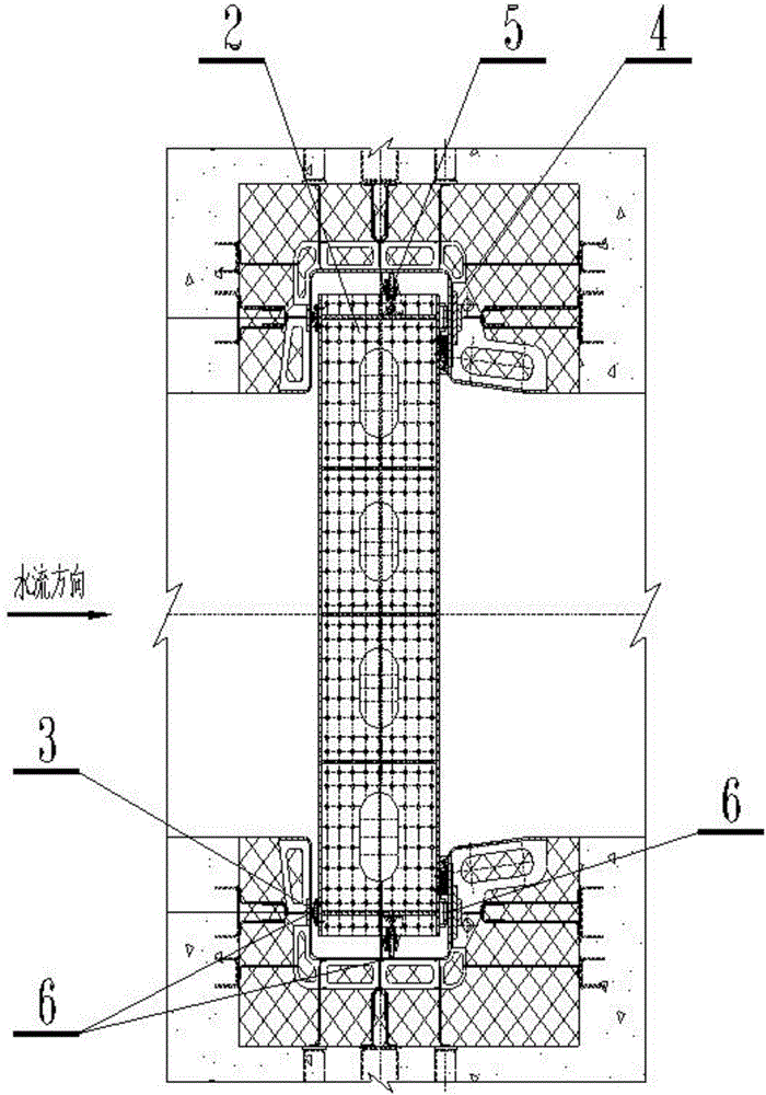
Figure 3
Abstract
Description
technical field
[0001] The invention relates to the technical field of metal structures in water conservancy and hydropower engineering, in particular to an improved method and structure for a plane sliding gate with extra high water head. Background technique
[0002] For ultra-high water head plane sliding gates, a water stop is usually installed downstream, and two rows of slider main support types are arranged on both sides of the downstream forward direction. This means that only the left and right sides of the gate are limited in the forward and reverse directions, and the gate is easily generated during the process of lowering the gate. Vibration, while the upstream panel of the plane sliding gate or the rear flange of the bottom main girder is generally a broken-line sudden change structure, which will lead to the disorder of the water flow and increase the force of the water flow on the gate. In addition, the top of the gate is unsupported as a long cantilever conti...
Examples
Embodiment Construction
[0032] The present invention will be further described in detail below in conjunction with the accompanying drawings and embodiments.
[0033] first look figure 1 , figure 1 A schematic diagram of the arrangement of the present invention is shown, from figure 1 It can be seen in the present invention that a super-high water head plane sliding gate 2 is arranged in the door slot 1 . Door slot 1 is provided with upstream high breast wall 7 and downstream high breast wall 8; more detailed structures, such as Figure 2-3 As can be seen from the figure, reverse supports 3 are provided on both sides and the top of the water-facing surface of the ultra-high head plane sliding gate 2, positive supports 4 are provided on both sides and the top of the backwater surface, and lateral supports 5 are provided on the sides; The groove 1 is provided with rails 6 corresponding to the positive and negative lateral support positions.
[0034] Figure 4 is the upstream view of the invention,...