
Method for controlling and regulating an internal combustion engine
一种内燃机、吸入节流阀的技术,应用在电气控制、发动机控制、燃料喷射控制等方向,能够解决不同等问题,达到应急运行稳定的效果
Patent Information
- Authority / Receiving Office
- CN · China
- Patent Type
- Patents(China)
- Current Assignee / Owner
- Publication Date
- 2021-02-26
Smart Images
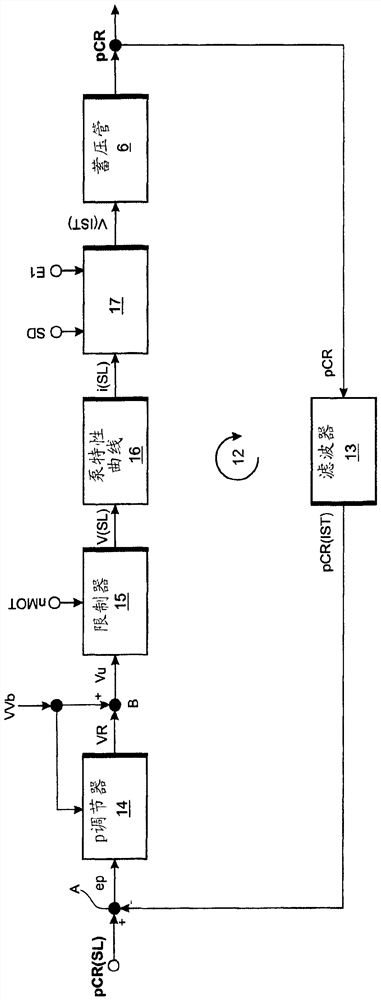
Figure 1 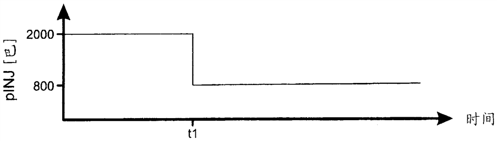
Figure 2 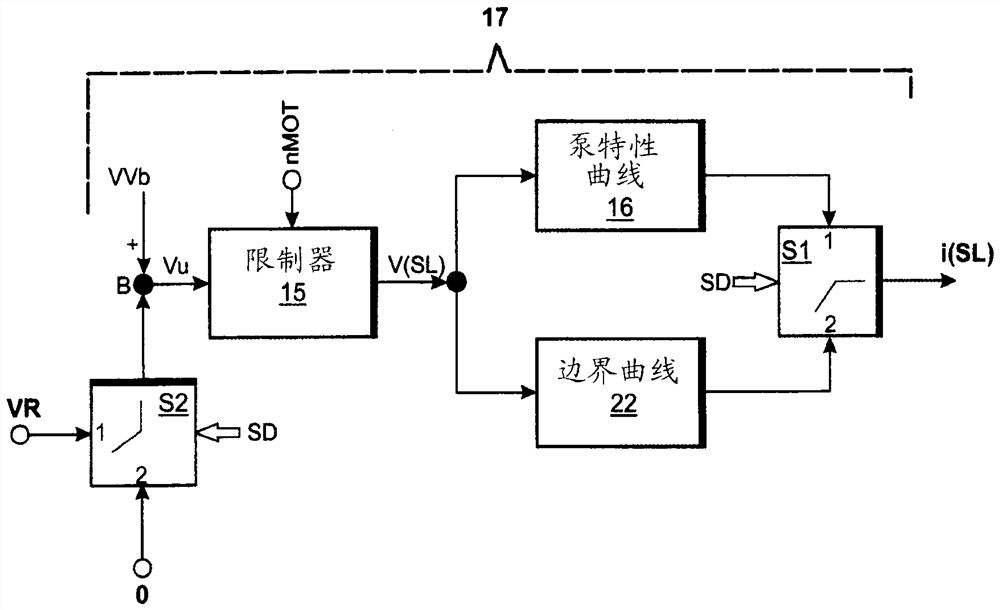
Figure 3
Abstract
Description
[0001] This application is a divisional application of the patent application with the application number CN201080047926.6, the application date is October 19, 2010, and the invention title is "Method for Controlling and Regulating Internal Combustion Engine". technical field
[0002] The invention relates to a method for controlling and regulating an internal combustion engine, in which the rail pressure (Raildruck) is adjusted in normal operation, switching from normal operation to emergency operation when a faulty rail pressure sensor is detected, and in emergency operation Control the accumulator pressure in the middle. Background technique
[0003] In internal combustion engines with a common rail system, the quality of the combustion is decisively determined by the pressure level in the rail. Therefore, the rail pressure is adjusted in order to comply with the statutory discharge limit values. Typically, the rail pressure regulation loop comprises a reference junction...
Examples
Embodiment Construction
[0026] figure 1 A system diagram showing an electronically controlled internal combustion engine 1 with a common rail system. The common rail system comprises the following mechanical components: a low-pressure pump 3 for delivering fuel from a fuel tank 2; a variable suction throttle valve 4 for influencing the fuel volume flow flowing through; A high-pressure pump 5 for fuel; an accumulator 6 for storing fuel and an injector 7 for injecting fuel into the combustion chamber of the internal combustion engine 1 . Optionally, a single accumulator can also be assigned to the common rail system, so that, for example, a single accumulator 8 is integrated in the injector 7 as an additional damper body. As protection against impermissibly high pressure levels in the accumulator 6, a passive pressure limiting valve 11 is provided, which opens, for example, at an accumulator pressure of 2400 bar and in the open state turns the Fuel drains from the pressure accumulator 6 into the fuel...