
Method and device for cell programmed layout seeding for cell impedance detection research
A technology of impedance detection and inoculation device, applied in the direction of program control, material resistance, computer control, etc., can solve the problems that the template inoculation layout cannot be changed, the cells cannot be adjusted and changed, and the automatic inoculation cannot be achieved, so as to achieve automatic inoculation and save energy. Eliminate the manual operation process and overcome the fixed and single effect of the inoculation layout
Patent Information
- Authority / Receiving Office
- CN · China
- Patent Type
- Patents(China)
- Current Assignee / Owner
- Publication Date
- 2019-12-03
Smart Images
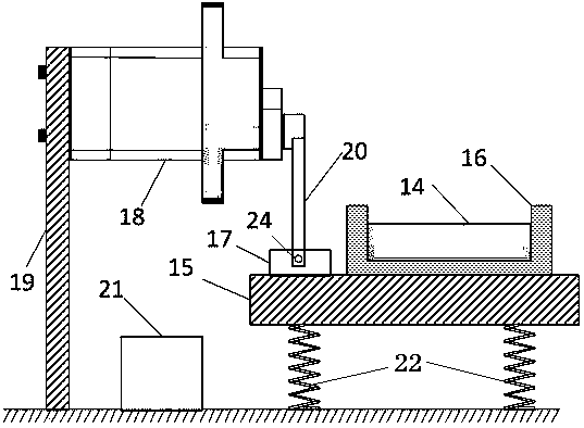
Figure 1 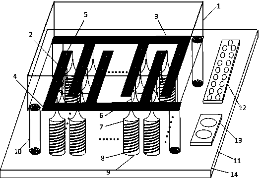
Figure 2 
Figure 3
Abstract
Description
technical field
[0001] The invention belongs to the field of cell impedance detection, in particular to a cell program-controlled layout inoculation method and device. Background technique
[0002] Cell impedance detection technology has been widely used in the research of cell biology. Impedance detection when cells are attached to interdigitated electrodes can effectively evaluate changes in cell activity, cell proliferation, cell migration speed, and cell resistance to viruses. ability etc. However, in the process of using interdigitated electrodes for cell impedance detection, the distribution of cells on the surface of the interdigitated electrode cell sensor (such as the uniformity of distribution, distribution position, and density of distribution, etc.) is closely related to the accuracy of cell impedance detection. . For the various cell layout inoculation methods, the current main researches are antibody inoculation method, template inoculation method, etc. Amon...
Examples
Embodiment Construction
[0021] see figure 1 The cell program-controlled layout inoculation device for cell impedance detection research of the present invention includes a cell impedance sensor 14, the cell impedance sensor 14 has a program-controlled layout inoculation function, and the cell impedance sensor 14 is just embedded in the groove alloy block 16, and the groove The alloy block 16 is fixed on the upper surface of the oscillating platform 15, and the oscillating platform 15 is driven by the steering gear 18 to vibrate up and down.
[0022] On the upper surface of the oscillating platform 15, a connecting bracket 17 is fixed beside the outer side of the groove alloy block 16, and the connecting bracket 17 is fixedly connected to the lower end of the steering gear cantilever 20 by fixing bolts 24. The steering gear cantilever 20 is vertically arranged, and its upper end is fixedly connected The output shaft of the steering gear 18 is arranged horizontally to drive the steering gear cantilever...