
Novel sausage airing hanging stand
A sausage, a new type of technology, applied in the field of drying racks, can solve problems such as being unsuitable for sausage drying, and achieve the effect of speeding up drying
Patent Information
- Authority / Receiving Office
- CN · China
- Current Assignee / Owner
- Publication Date
- 2018-02-06
- Estimated Expiration
- Not applicable · inactive patent
Smart Images
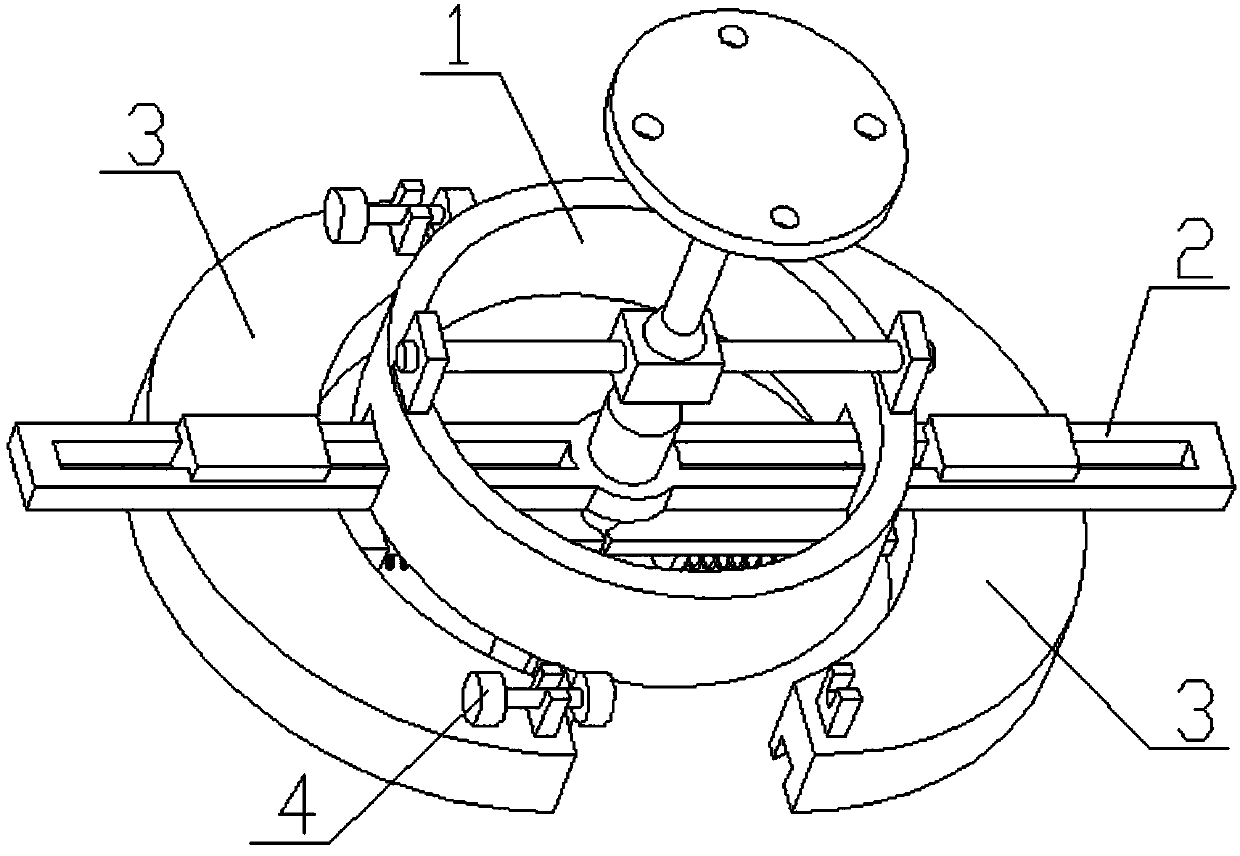
Figure 1 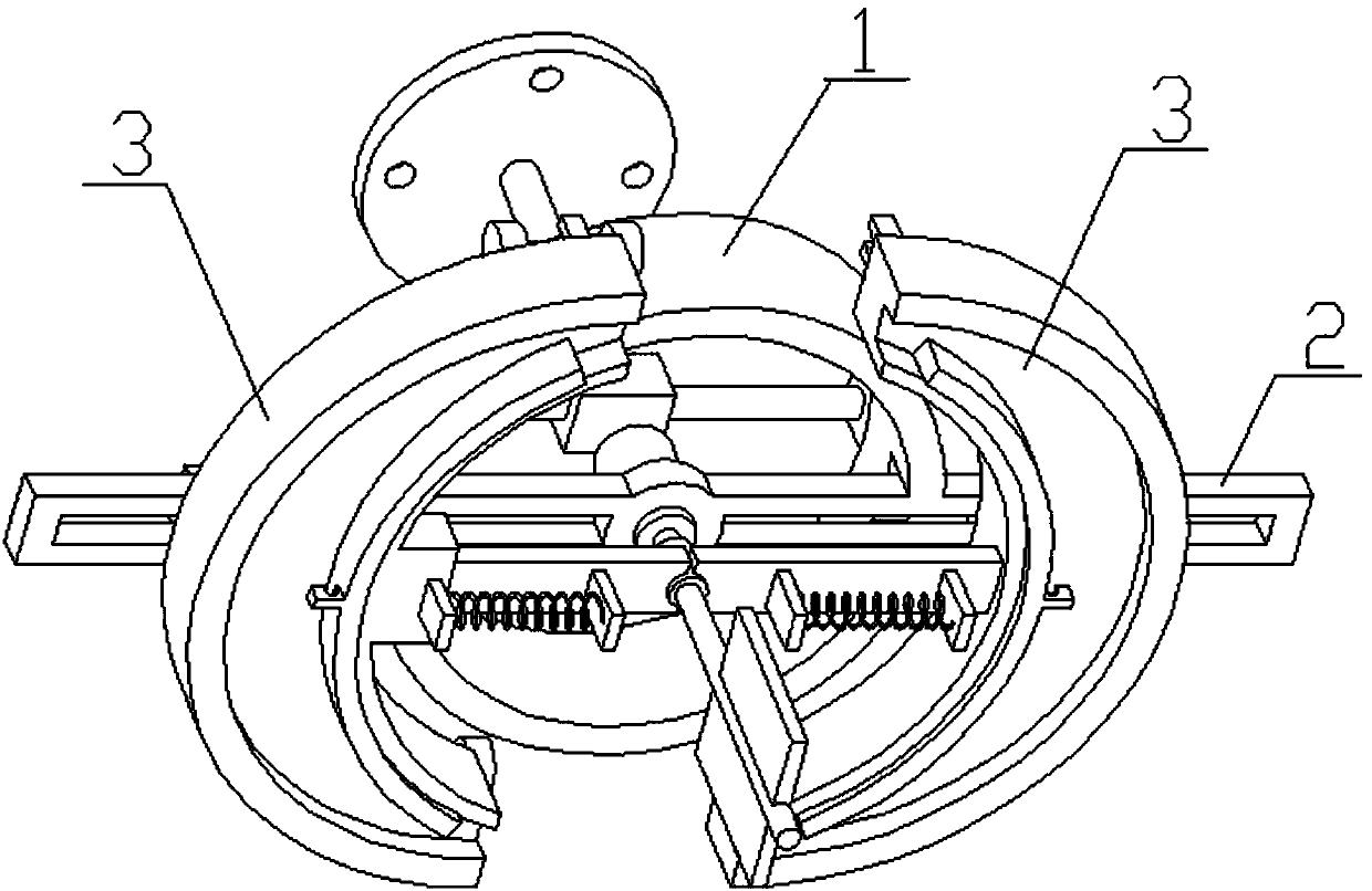
Figure 2 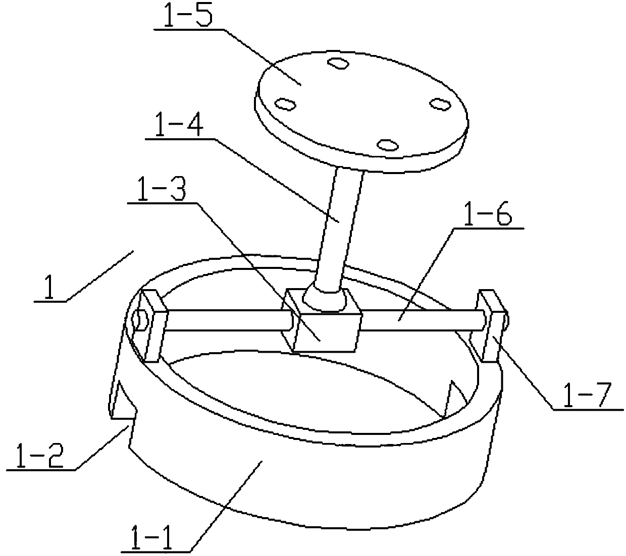
Figure 3
Abstract
Description
technical field
[0001] The invention relates to a drying rack, in particular to a novel sausage drying rack. Background technique
[0002] The application number is CN201520267064.8, a drying rack. The utility model relates to a drying rack. The drying rack includes: a stand, a number of fixed rods evenly distributed on the stand, and the quartz tube Placed between two adjacent fixed rods, the drying rack is used to dry the quartz tubes, and it is characterized in that: the drying rack is slope-shaped, and several rows of the quartz tubes are placed obliquely on the drying rack. On the drying rack, the drying rack also includes some baffles perpendicular to the fixed rod, one end of the quartz tube leans against the baffle, the drying rack is slope-shaped, and when the quartz tube is dried, The quartz tube is placed obliquely on the drying rack, so that the liquid in the quartz tube can flow out completely, reducing the drying time, and at the same time ensuring that there ...
Examples
specific Embodiment approach 1
[0025] Combine below Figure 1-8 Describe this embodiment, the present invention relates to a drying rack, more specifically a new type of sausage drying hanger, including a suspension rack 1, a slideway assembly 2 and a drying assembly 3, the device can hang the sausage ring on it And the device can swing with the wind. After the two drying components are combined, the sausage will not fall even if the device swings, and the device is provided with blades that can blow the air to speed up the drying of the sausage.
[0026] The suspension frame 1 includes a cylindrical seat 1-1 and a cylindrical lower groove 1-2, and the left and right sides of the lower end of the cylindrical seat 1-1 are provided with a cylindrical lower groove 1-2;
[0027] Described slide way assembly 2 comprises chute rod 2-1, chute 2-2, motor 2-3, long bearing 2-4, shaft rod 2-5 and blade 2-6, the chute rod 2-1 The left and right ends are provided with a chute 2-2, the motor 2-3 is fixedly connected to...