
A detection robot and a method for detecting the pouring quality of steel pipe concrete using the detection robot
A concrete-filled steel tube and robot technology, which is used in measuring devices, processing response signals of detection, and analyzing solids using sonic/ultrasonic/infrasonic waves, which can solve problems such as difficulty in observation and detection.
Patent Information
- Authority / Receiving Office
- CN · China
- Patent Type
- Patents(China)
- Current Assignee / Owner
- Publication Date
- 2020-10-30
Smart Images
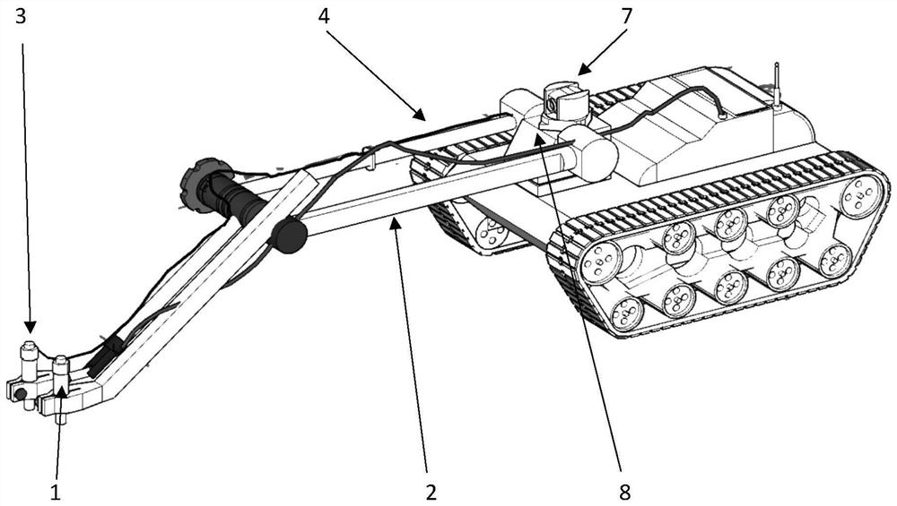
Figure 1 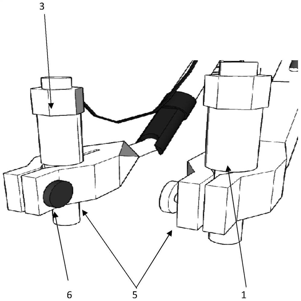
Figure 2 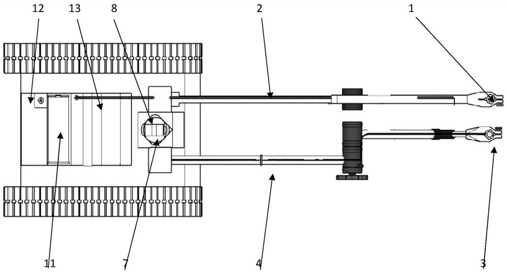
Figure 3
Abstract
Description
technical field
[0001] The invention relates to the field of construction engineering, and mainly relates to a detection robot and a method for using the detection robot to detect the pouring quality of steel pipe concrete. Background technique
[0002] Concrete-Filled Steel Tube composite structure refers to the composite structure formed by filling concrete in steel pipes. The interaction between steel pipes and concrete during the stress process makes the concrete in a complex stress state, thereby improving the strength of the concrete. Plasticity and toughness are improved. The composite structure of steel tube concrete fully utilizes the advantages of steel and concrete. It has the following advantages: light weight, fatigue resistance, high strength, impact resistance and good ductility in terms of mechanical properties, light erection in terms of construction performance, labor and material saving, and convenient construction. Due to the advantages of fast speed, it...
Examples
Embodiment
[0046] Use artificial percussion listening method or infrared thermal imaging technology to quickly detect the overall structure of the steel pipe concrete to be detected, and initially determine the area where local void damage may occur;
[0047] Such as Figure 7 As shown in , the surface of the steel shell in the area where local void damage may occur is divided into 10×10 grids with a spacing of 25mm, and the microphones are placed 50mm above the intersection points of each column of grids in turn;
[0048] Tap each grid intersection point in each row and column in turn, pick up the sound pressure signal of the microphone directly above the point, and make a frequency response function with the force signal of the hammer, and extract its frequency response by CMIF method For the first obvious frequency peak, calculate the modal compliance sound pressure form at this order frequency. For the above grid, obtain the modal compliance values at each point, as shown in Table ...