
Lifting mechanism used for AGV
A lifting mechanism and driving motor technology, applied in the field of AGV vehicles, can solve the problems of complex structure and poor operation stability of the lifting mechanism, and achieve the effects of high transmission efficiency, stable lifting operation and reasonable structure
Patent Information
- Authority / Receiving Office
- CN · China
- Patent Type
- Applications(China)
- Current Assignee / Owner
- Publication Date
- 2018-07-27
Smart Images
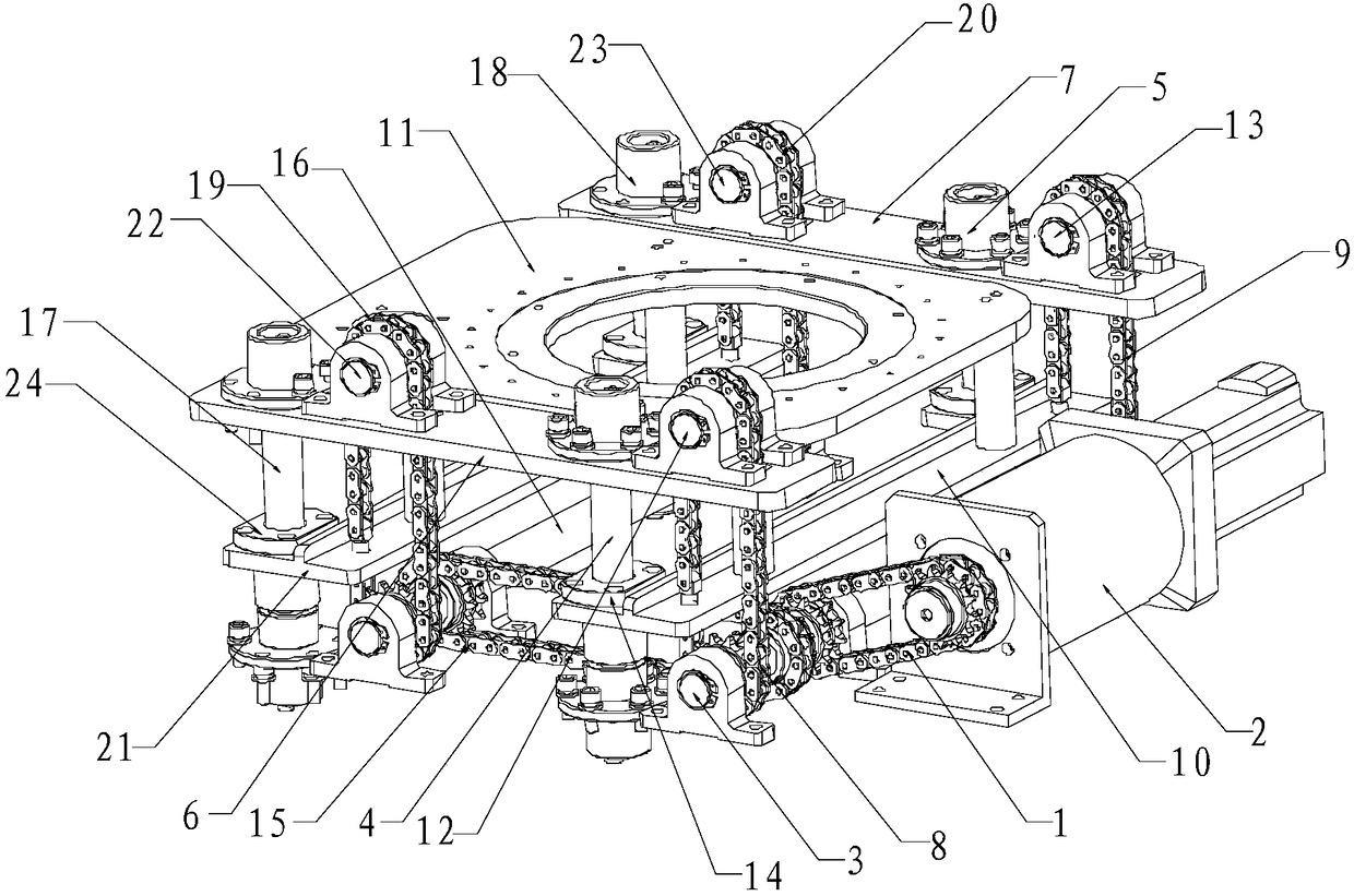
Figure 1
Abstract
Description
technical field
[0001] The invention relates to the technical field of an AGV, in particular to a lifting mechanism for an AGV. Background technique
[0002] With the rapid development of industrial automation, enterprises have higher and higher requirements for the automation of AGV vehicle operation process, and require AGV vehicles to have automatic loading and unloading. Therefore, it is necessary to set up corresponding automatic lifting devices for AGV vehicles. The lifting mechanism of the AGV car in the prior art has a complicated structure, and the operation stability is relatively poor, so the use has great limitations. Contents of the invention
[0003] The technical problem to be solved by the present invention is how to provide a lifting mechanism for an AGV, which has a reasonable structure, high transmission efficiency, and more stable lifting operation.
[0004] The technical scheme that the present invention solves the problems of the technologies describ...
Examples
Embodiment Construction
[0029] The principles and features of the present invention are described below in conjunction with the accompanying drawings, and the examples given are only used to explain the present invention, and are not intended to limit the scope of the present invention.
[0030] like figure 1 As shown, the invention discloses a lifting mechanism for an AGV car.
[0031] In a preferred embodiment, the lifting mechanism of the present invention for an AGV car includes a motor output chain 1, a drive motor 2, a first transmission shaft 3, a first guide shaft 4, a second guide shaft 5, a first fixed plate 6, The second fixed plate 7, the first traction chain 8, the second traction chain 9, the first guide plate 10 and the supporting plate 11, one end of the motor output chain 1 is sleeved on the output end of the drive motor 2, and the other end Sleeved on the first transmission shaft 3; the first guide shaft 4 and the second guide shaft 5 are arranged at intervals along the length dire...